Contents
- Understanding Oxygen Sensor Functionality
- Types of Oxygen Sensors
- Sensor Locations in Vehicles
- Recognizing Symptoms of a Failing Oxygen Sensor
- Testing Methods and Required Tools
- Tools You’ll Need:
- Method 1: Using an OBD-II Scanner
- Step-by-Step OBD-II Testing Procedure:
- Method 2: Multimeter Testing
- Testing Voltage Output:
- Creating Rich and Lean Conditions for Testing
- Method 3: Testing the Heater Circuit
- Interpreting Test Results
- Maintenance Guidelines and Replacement Considerations
- Conclusion
- Need Expert Assistance?
The oxygen sensor (O2 sensor) plays a critical role in your vehicle’s engine management system, measuring oxygen content in exhaust gases and helping maintain optimal air-fuel ratios. When functioning correctly, it ensures efficient combustion, reduces emissions, and protects your catalytic converter. In this guide, we will explain how to test an oxygen sensor using various methods, from basic multimeter checks to advanced diagnostic procedures.
Understanding Oxygen Sensor Functionality
Oxygen sensors, also known as lambda sensors, monitor oxygen levels in exhaust gases and send this vital information to the Engine Control Unit (ECU). The ECU then adjusts the air-fuel mixture based on this feedback, ensuring optimal performance, fuel efficiency, and lower emissions.
Types of Oxygen Sensors
- Narrowband (Zirconia) Sensors – The most common type, producing voltage based on the oxygen level difference between exhaust gases and ambient air.
- Wideband Sensors – More advanced, providing real-time feedback for precise fuel control.
Sensor Locations in Vehicles
Modern vehicles usually have multiple oxygen sensors located in the exhaust system:
- Upstream Sensors (Before the Catalytic Converter): Control the fuel mixture.
- Downstream Sensors (After the Catalytic Converter): Monitor catalytic converter efficiency.
Recognizing Symptoms of a Failing Oxygen Sensor
A failing oxygen sensor can cause various performance and emissions-related issues, such as:
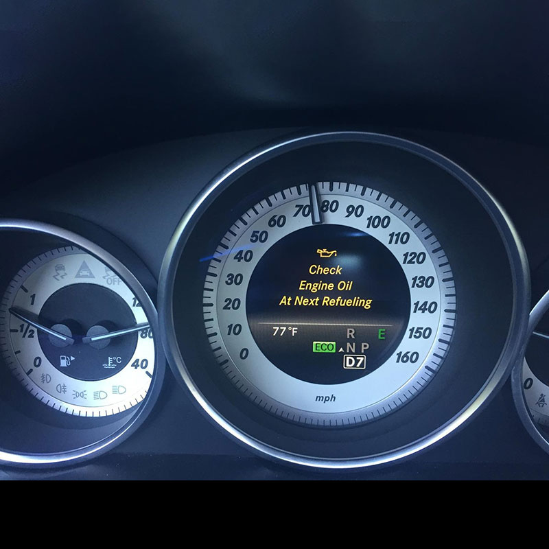
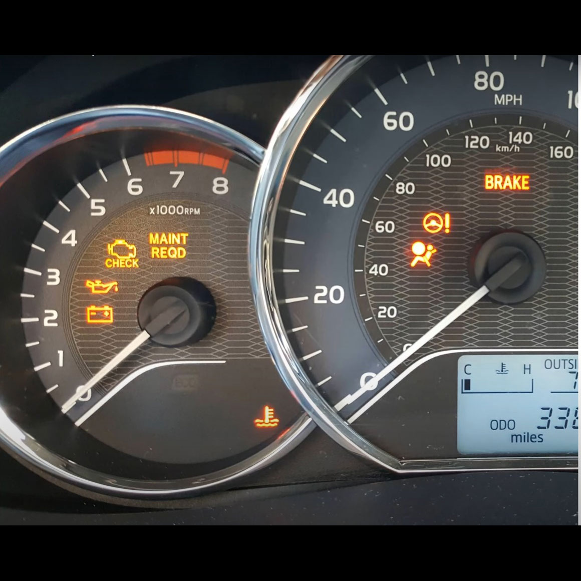
- Check engine light illumination
- Decreased fuel efficiency
- Rough idling or engine misfires
- Failed emissions tests
- Sulfuric (rotten egg) smell from the exhaust
- Poor overall engine performance
If your vehicle exhibits these symptoms, testing the oxygen sensor is crucial before replacing components.
Testing Methods and Required Tools
Tools You’ll Need:
- Digital Multimeter (DMM)
- OBD-II Scanner (for vehicles manufactured after 1996)
- Back-probe or piercing probe test leads
- Vehicle service manual (for sensor specifications)
- Protective gloves and eyewear
- Oxygen sensor wrench (if removal is necessary)
Method 1: Using an OBD-II Scanner
One of the easiest ways to test an oxygen sensor is by using an OBD-II scanner:
Step-by-Step OBD-II Testing Procedure:
- Warm up the engine for at least 20 minutes to bring the oxygen sensor to operating temperature.
- Connect the OBD-II scanner to the vehicle’s diagnostic link connector (DLC) under the dashboard.
- Start the engine and navigate to the oxygen sensor readings on the scanner.
- Analyze the voltage readings:
- Upstream sensors should fluctuate between 0.1V and 0.9V (100mV to 900mV).
- Downstream sensors should maintain relatively steady readings around 0.45V.
- If readings remain static or show no signal, the sensor likely needs replacement.
Method 2: Multimeter Testing
If an OBD-II scanner is unavailable, a digital multimeter can provide an alternative method to test the sensor’s voltage output.
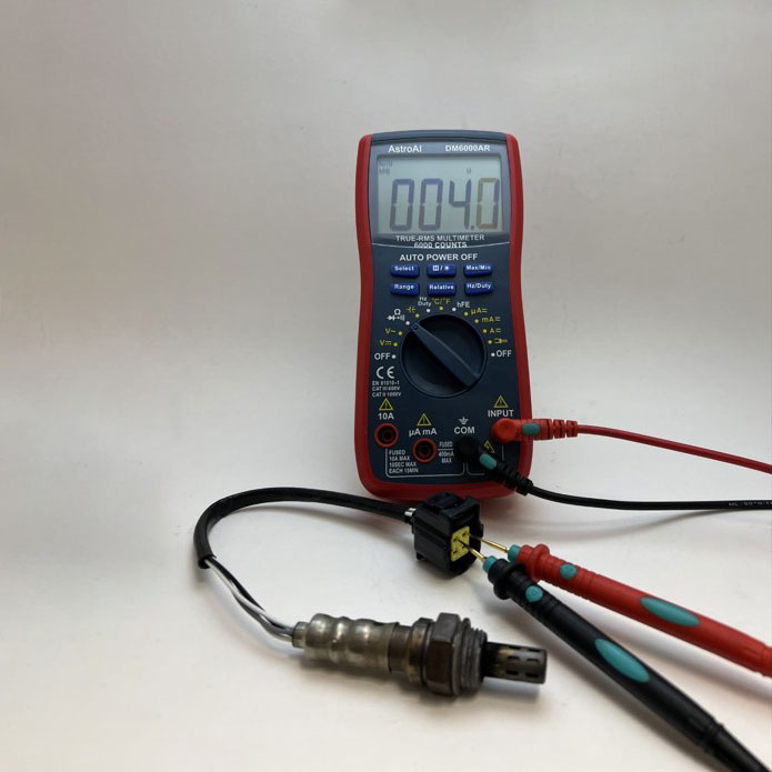
Testing Voltage Output:
- Identify the sensor’s signal wire using a wiring diagram.
- Set the multimeter to DC voltage (2V range).
- Connect the red probe to the sensor’s signal wire and the black probe to ground.
- Observe the voltage readings with the engine running:
- A properly functioning sensor should fluctuate between 0.1V and 0.9V.
- A faulty sensor will have static or no voltage changes.
Creating Rich and Lean Conditions for Testing
To verify sensor responsiveness:
- To simulate a lean condition, disconnect the PCV hose—voltage should drop to around 0.2V.
- To simulate a rich condition, restrict the air intake—voltage should increase to about 0.8V.
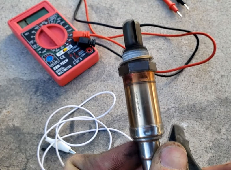
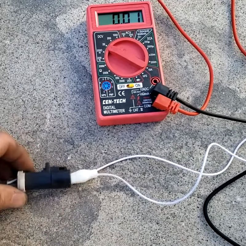
Method 3: Testing the Heater Circuit
Most modern oxygen sensors include an internal heater for quicker warm-up. To test the heater circuit:
- Turn off the engine and let it cool.
- Disconnect the sensor’s electrical connector.
- Set the multimeter to resistance (ohms, 200-ohm range).
- Measure the resistance across the heater circuit pins.
- A resistance reading between 2-14 ohms indicates a functioning heater. No reading suggests a failed heater element, requiring sensor replacement.
Interpreting Test Results
- Voltage Fluctuation: A healthy upstream sensor should rapidly change between low (0.1-0.3V) and high (0.8-0.9V) values.
- Response Time: A functional sensor should transition between voltage states within 300 milliseconds.
- Downstream Sensor Stability: Should maintain steady readings around 0.45V—fluctuations indicate possible catalytic converter issues.
Maintenance Guidelines and Replacement Considerations
- Test oxygen sensors every 60,000 miles for heated sensors and 30,000 miles for unheated sensors.
- Even if an oxygen sensor passes voltage tests, a slow-responding sensor can negatively impact fuel economy and performance.
- Regular inspection and cleaning of sensors help prevent premature failure.
Conclusion
Testing an oxygen sensor is an essential diagnostic process that helps identify potential issues before they lead to costly repairs. While an OBD-II scanner provides the most accurate assessment, multimeter testing offers a practical alternative for DIY mechanics.
By following these procedures, you can accurately determine your oxygen sensor’s health, optimize your vehicle’s fuel efficiency, and prevent unnecessary part replacements.
Need Expert Assistance?
If you’re facing oxygen sensor issues and need professional diagnostic, coding, or programming support, AutoExplain is here to help! Contact us for expert guidance and repair solutions.
📞 WhatsApp: +84967469410
🌐 Website: AutoExplain