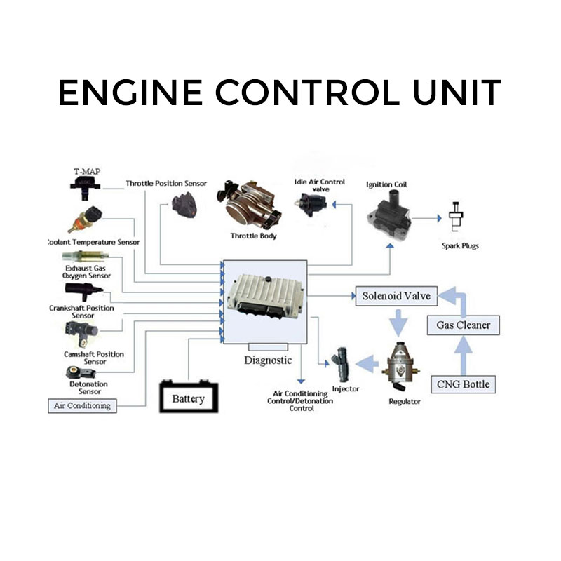
The Electronic Control Unit (ECU) is the brain of modern vehicles, responsible for processing real-time data, executing control algorithms, and managing various car subsystems. Understanding the components of ECU is crucial for automotive engineers, technicians, and car enthusiasts looking to diagnose, repair, or enhance vehicle performance. This article will explore the car ECU components in detail.
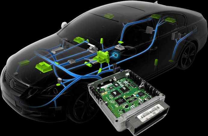
The Electronic Control Unit (ECU) is a central computer in a car that manages a variety of systems based on input it receives from sensors. There are many types of ECUs in a vehicle: Engine Control Module (ECM), Transmission Control Module (TCM), Body Control Module (BCM), Airbag Control Unit, ABS Control Unit, and more.
Each ECU processes sensor signals, makes logical decisions, and sends output commands to actuators to optimize vehicle performance, emissions, safety, and efficiency.
Fuel delivery control
Ignition timing
Idle speed regulation
Emission systems control
Boost and torque management
Safety (airbag, ABS, collision systems)
Understanding the components of ECU is crucial for diagnosing faults, performing coding/programming, or even doing component-level repair. These internal parts work in harmony to ensure the ECU functions reliably under extreme automotive conditions.
Here’s a quick list of key ECU components:
| Component | Function |
|---|---|
| Microcontroller Unit (MCU) | Main processor that executes the control logic |
| Volatile vs. Non-Volatile Storage | Stores firmware and calibration maps |
| EEPROM | Stores learned data, DTCs, and adaptation values |
| RAM | Temporary memory used during operation |
| Input/Output Drivers | Interface with sensors and actuators |
| Analog-to-Digital Converters (ADC) | Convert sensor analog signals to digital |
| Power Supply & Voltage Regulator | Maintain consistent power to circuits |
| CAN/LIN/FlexRay Transceivers | Communication with vehicle networks |
| Oscillator/Clock | Timekeeping for real-time operations |
| PCB (Printed Circuit Board) | Physical platform for all components |
At the heart of an ECU is the microcontroller unit (MCU), which executes firmware algorithms, processes sensor inputs, and generates actuator commands. Modern MCUs use multi-core architectures to handle complex tasks, such as:
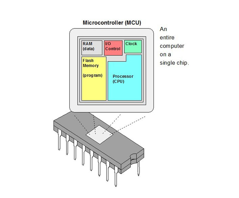
3.1.1. What Is an MCU in the ECU?
A microcontroller is a compact integrated circuit (IC) that contains a:
Central processor (CPU)
Random Access Memory (RAM)
Read-Only Memory (ROM/Flash)
Input/Output (I/O) ports
Timers
Communication modules (CAN, SPI, UART)
Unlike general-purpose CPUs, MCUs used in automotive ECUs are specifically designed for deterministic, real-time control in harsh operating conditions (temperature extremes, voltage fluctuations, EMI, etc.).
3.1.2. Key Features of Automotive-Grade MCUs
| Function | Description |
|---|---|
| Sensor Data Processing | Reads inputs from crankshaft, throttle, MAF, coolant sensors, etc. |
| Actuator Control | Sends timed signals to injectors, coils, VVT solenoids, throttle motors |
| Control Algorithms Execution | Runs closed-loop PID control, engine mapping, torque calculations |
| Safety & Redundancy | Manages limp modes, fault detection, and fail-safe behavior |
| Communication Handling | Exchanges data with other ECUs via CAN, LIN, FlexRay, etc. |
| Diagnostic Management | Stores DTCs, freeze frame data, monitors readiness flags |
| Timing & Synchronization | Keeps operations synchronized with crank angle, ignition timing |
The Electronic Control Unit (ECU) relies heavily on different types of memory components to perform real-time calculations, retain calibration data, and store diagnostic information. These memory elements fall into two major categories: volatile memory and non-volatile memory.
3.2.1. Non-Volatile Memory (Persistent Data Storage)
Non-volatile memory retains its data even when the ECU is powered off. It’s crucial for storing information that must persist across engine cycles, servicing, or even battery disconnections. Modern ECUs use multiple types of non-volatile storage:
3.2.1.1. Flash Memory
This is the main memory type used to store the ECU’s firmware, including:
Flash memory is also where tuning software modifies parameters, and where manufacturers push software updates.
Flash Memory Characteristics:
Example: A performance tuner adjusts the ignition timing map stored in flash memory to increase horsepower.
3.2.1.2. EEPROM (Electrically Erasable Programmable ROM)
EEPROM is a smaller but essential memory type used for storing vehicle-specific data and dynamic learning values. Unlike flash, EEPROM can be rewritten at the byte level without erasing large blocks.
Data stored in EEPROM includes:
EEPROM Characteristics:
Example: When you replace an ECU, you must copy the EEPROM data (especially the IMMO data) to the new unit to make the vehicle start properly.
3.2.2. Volatile Memory (Real-Time Data Processing)
Volatile memory is a type of memory that loses all stored data when power is removed. In the context of an automotive ECU (Electronic Control Unit), volatile memory plays a vital role in the real-time processing of information during engine operation — but it does not store permanent data.
The most common form of volatile memory in ECUs is RAM (Random Access Memory).
Just like your computer uses RAM to temporarily hold open applications and files, a vehicle ECU uses RAM to:
This memory is extremely fast and efficient, allowing the microcontroller to process inputs and generate outputs within milliseconds.
*How RAM Works in an ECU
The input/output system of an ECU refers to the circuitry and signal conditioning components that receive and process input signals from sensors (inputs) and generate and transmit output signals to actuators (outputs)
These components include:
Analog-to-Digital Converters (ADC)
Digital Input Buffers
Digital Output Drivers (FETs, transistors)
Pulse Width Modulation (PWM) modules
Sensor interface circuits (voltage dividers, filters, amplifiers)
3.3.1. INPUT: How the ECU Reads Sensor Data
Modern vehicles are packed with sensors that monitor everything from engine temperature to pedal position. These sensors output either:
Analog signals (varying voltage levels, e.g., 0–5V)
Digital signals (ON/OFF or frequency-based pulses)
The ECU’s input circuits process these in the following ways:
3.3.1.1. Analog-to-Digital Converters (ADCs)
Convert analog sensor signals into digital values:
3.3.1.2. Digital Inputs
Handles binary signals from sensors and switches:
3.3.2. OUTPUT: How the ECU Controls Actuators
After processing sensor data and executing control logic, the ECU sends commands to various actuators. These include:
Fuel injectors
Ignition coils
Turbo actuators
Idle control valves
EGR solenoids
Electric fans
The output stage of the ECU ensures the signal is:
At the correct voltage and current
Properly timed (especially for fuel and ignition)
Durable under electrical load
3.3.2.1. Output Drivers (Transistors, FETs)
These electronic switches are capable of turning on/off high-current actuators. The microcontroller sends low-power signals to these switches, which then control the flow of current to the actuator.
Common Output Driver Types:
MOSFETs (Metal-Oxide-Semiconductor FETs)
Bipolar transistors
Relay control circuits (for higher loads)
When an injector driver fails, the injector may stay open (flooding) or not open at all (misfire).
3.3.2.2. Pulse Width Modulation (PWM)
Some actuators (like fuel injectors, EGR valves, or throttle bodies) require variable control, not just ON/OFF.
The ECU uses PWM signals to modulate:
Duty cycle (on-time percentage)
Frequency (speed of switching)
This allows for fine-tuned control of systems like:
Idle speed
Boost pressure
Air/fuel delivery
3.3.3. Bidirectional Inputs/Outputs
Some ECU pins are bidirectional — meaning they can act as both inputs and outputs, depending on the condition.
Example:
OBD-II communication lines (K-Line, CAN)
Ignition switch input that also controls wake-up signal
These pins use tri-state logic or software-controlled directionality.
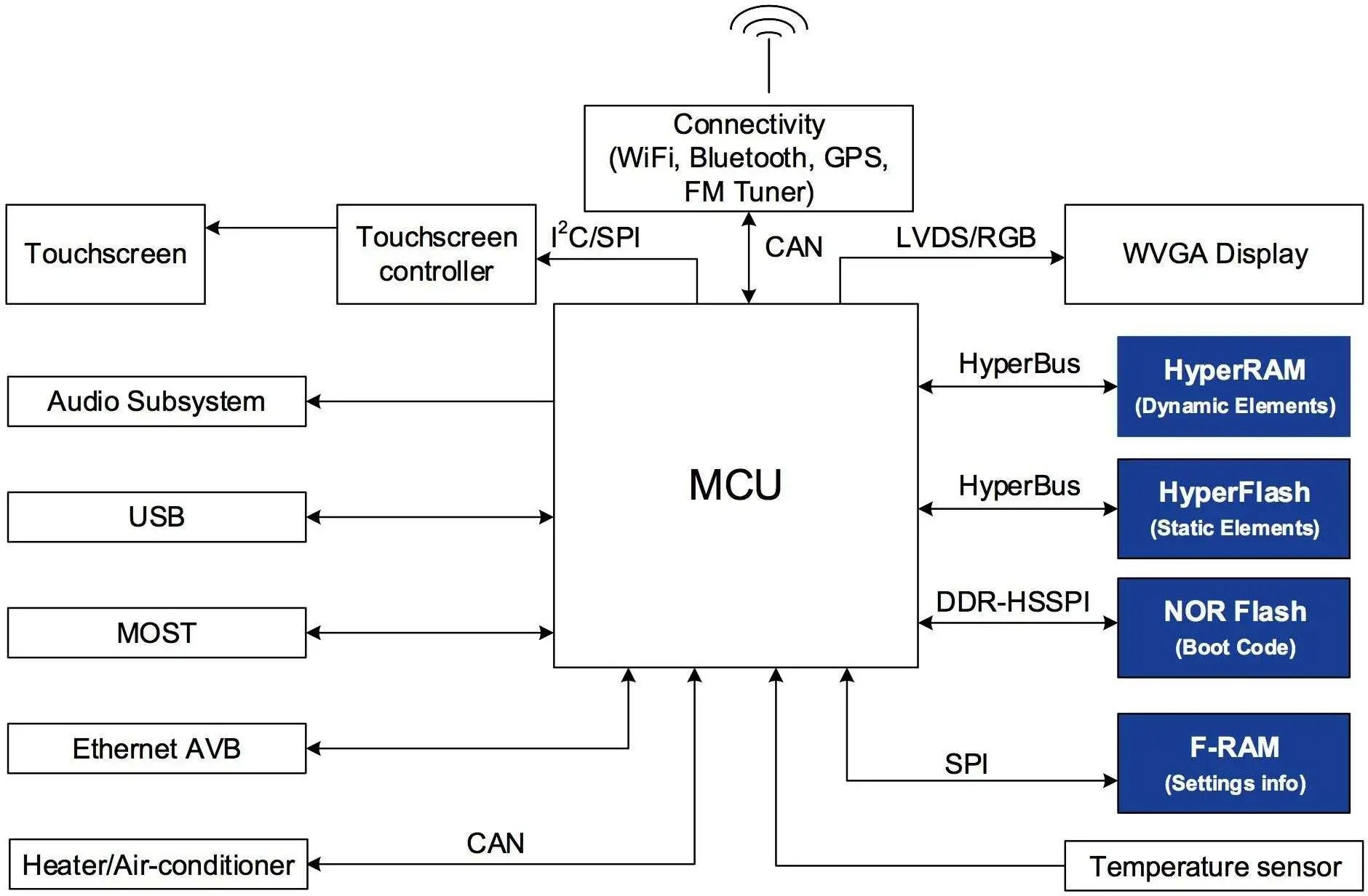
Modern ECUs rely on high-speed vehicle communication networks to share data efficiently.
3.4.1. Controller Area Network (CAN)
The CAN bus is the most widely used automotive communication protocol. It allows multiple ECUs to communicate over a twisted-pair cable with high noise resistance and speed.
Speed: Up to 1 Mbps (CAN 2.0), or 5–8 Mbps with CAN FD
Topology: Multi-master, peer-to-peer
Use Cases: Engine control, transmission, ABS, airbag systems, steering
Advantages: Real-time messaging, built-in error handling, arbitration for priority messaging
In every ECU that supports CAN, there is a CAN transceiver chip and associated hardware responsible for sending/receiving data and ensuring voltage level compliance.
Example: The Engine ECU may broadcast real-time RPM data to the Instrument Cluster ECU via CAN every 10 milliseconds.
3.4.2. Local Interconnect Network (LIN)
The LIN bus is used in less time-critical, cost-sensitive applications like:
Door locks
Seat motors
Interior lights
Mirror adjustments
Speed: Up to 20 kbps
Topology: Master/slave
Typical Setup: One master ECU controls multiple slave devices
LIN is often used to reduce wiring complexity and cost in systems that don’t require the high speed or bandwidth of CAN.
Example: A Door Module (master) might send commands to mirror fold motors (slaves) over LIN.
3.4.3. Automotive Ethernet
As vehicles adopt more data-hungry systems (e.g., 360° cameras, infotainment, over-the-air updates), traditional protocols like CAN begin to hit bandwidth limits. Automotive Ethernet addresses this need.
Speed: 100 Mbps to 10 Gbps
Use Cases: Radar, LiDAR, cameras, infotainment, OTA firmware updates
Architecture: Point-to-point or switched network
Tools Needed: Specialized Ethernet analyzers and diagnostic tools
Many modern ECUs now include Ethernet PHY transceivers and are preconfigured for DoIP (Diagnostics over IP).
3.4.4. FlexRay
FlexRay is a high-bandwidth, deterministic, and redundant communication interface used in safety-critical systems, such as:
Advanced driver assistance systems (ADAS)
Brake-by-wire
Steer-by-wire
Speed: Up to 10 Mbps
Topology: Dual-channel (redundant)
Key Advantage: Highly predictable timing, fault-tolerant communication
Example: In high-end vehicles, FlexRay is used to synchronize steering, braking, and camera inputs with extreme timing precision.
The ECU typically receives power directly from the vehicle’s battery (12V or 24V depending on the vehicle type), through the ignition switch or a relay-controlled power circuit. However, most internal ECU circuits, especially logic and digital components, do not operate directly on 12V. Instead, they require lower, regulated voltages like 5V, 3.3V, or 1.8V. That’s where the ECU’s voltage regulation system comes into play.
3.5.1. Voltage Regulation
3.5.2. Protection Mechanisms
ECUs use preprocessing circuits to improve sensor signal integrity:
ECUs integrate active and passive cooling strategies to ensure reliability:
To prevent hacking and data tampering, modern ECUs implement multi-layered security:
The Electronic Control Unit (ECU) is a tightly integrated system. If one or more of its internal components begin to malfunction — whether it’s a sensor input, power regulator, memory chip, or communication interface — the vehicle’s performance, reliability, and even safety can be seriously affected.
Understanding how a failing ECU component manifests in real-world symptoms is crucial for automotive technicians, DIY mechanics, and anyone involved in ECU diagnostics or tuning.
When ECU components begin to fail, the symptoms vary depending on which subsystem is affected. Here are the most common scenarios and their telltale signs:
Complete ECU failure or no communication with diagnostic tools
Random logic errors or incorrect actuator commands
Vehicle may crank but not start, or enter limp mode
Inconsistent behavior, such as RPM surges, fuel cutoffs, or ignition misfires
Loss of coding or VIN (EEPROM issues)
Start errors due to immobilizer mismatch
Check engine light stays on even after clearing DTCs
Failed reprogramming or flashing attempts
Random or invalid fault codes (e.g., “U-code” network errors)
Sensors show incorrect live data despite being good
Injectors, ignition coils, or actuators don’t receive commands
CAN line errors due to shorted I/O pins
One component (e.g., cooling fan) runs continuously or not at all
ECU won’t power up or dies during cranking
No 5V sensor reference voltage
Blown internal voltage regulators due to jump-start or alternator spike
Burnt smell or heat marks on the ECU board
“No communication with ECU” message on diagnostic scanner
Other modules can’t receive signals (e.g., ABS can’t see engine RPM)
Error codes like U0100 (Lost Communication with ECM/PCM)
Gateway modules stuck or flooding the network with errors
Here is a curated list of error codes from Audi, Mercedes, and BMW that are commonly related to ECU components — including power issues, internal hardware faults, memory corruption, communication problems, and control module failures. These codes typically indicate that something is wrong inside the ECU, or between the ECU and other parts of the system.
| Code | Description |
|---|---|
| Audi P0601 | Internal Control Module Memory Check Sum Error |
| Audi P0606 | ECM/PCM Processor Fault |
| Audi P1602 | Power Supply Terminal 30: Voltage Too Low |
| Audi P0603 | Internal Control Module Keep Alive Memory (KAM) Error |
| Audi P1570 | Engine Control Module Locked (immobilizer active) |
| Audi U0100 | Lost Communication with ECM/PCM “A” |
| Audi P0658 | Actuator Supply Voltage “A” Circuit Low |
| Audi P310B | Low Pressure Fuel Regulation: Control Range Not Reached (can be caused by ECU driver failure) |
| Audi P0607 | Control Module Performance |
| Code | Description |
|---|---|
| Mercedes B104A | N3/10 (ME-SFI [ME] control unit): Internal fault |
| Mercedes P060A00 | Internal Control Module Monitoring Processor Performance |
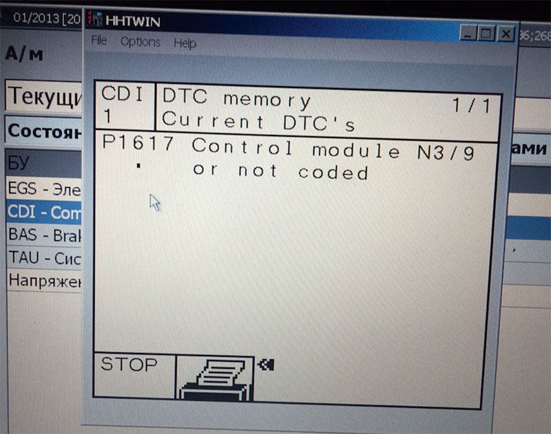
| Mercedes P1617 | Internal fault in control unit (often related to flash corruption or checksum error) |
| Mercedes P13E0 | Control module has internal fault (common in CDI ECUs) |
| Mercedes U0100 | No communication with ECM/PCM (CAN fault or ECU dead) |
| Mercedes P1630 | No communication with throttle actuator control |
| Mercedes B2200 | Control unit fault — often occurs after failed programming or due to corrupted EEPROM |
| Mercedes P1999 | Internal control module fault (usually requires ECU replacement or flashing) |
| Mercedes P16A3 | Control unit supply voltage too low (power management issue) |
| Code | Description |
|---|---|
| BMW 2F44 | EWS (immobilizer) manipulation or ECU mismatch |
| BMW 30BA | DME: Internal fault (Flash or MCU error) |
| BMW 2DEC | Power management: Standby current violation |
| BMW 2F4A | DME: No communication with CAS (ECU handshake failed) |
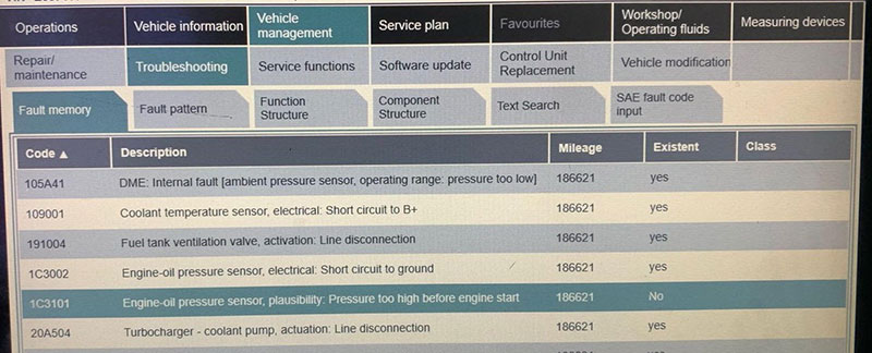
| BMW 105A41 | DME: Internal fault [ambient pressure sensor, operating range: pressure too low] |
| BMW A0B4 | CAS: Engine Start Operation, Faulty |
| BMW CD9420 | DME/DDE: Control unit, internal fault |
| BMW D90D02 | ECU voltage supply fault (under/overvoltage) |
| BMW 9308 | FRM (Footwell Module) internal fault – common after voltage spikes during battery replacement |
| BMW D515 | No communication with DME (CAN bus or ECU damaged) |
Diagnosing a faulty ECU isn’t always straightforward. Unlike a typical sensor or actuator that can be swapped out and tested quickly, the ECU is a complex unit with many internal subsystems — including power regulation, memory, I/O logic, microcontrollers, and communication interfaces — all of which can fail independently or intermittently.
To accurately diagnose ECU component failure, a technician must combine traditional electrical testing methods with advanced diagnostic tools and logical troubleshooting. Below is a step-by-step breakdown of how to approach ECU diagnostics effectively.
Step 1: Confirm Basic Power and Ground Supply
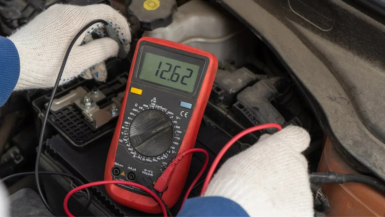
Before suspecting an internal ECU fault, always start by verifying the power and ground integrity at the ECU connector. Many ECU-related symptoms (no communication, intermittent signals, erratic sensor data) are often caused by corroded or broken wires, poor grounds, or voltage drops.
Checkpoints:
Battery voltage at ECU’s main power pin (typically 12V–13.8V)
Clean and tight ECU ground connections (less than 0.1 ohm resistance)
Voltage drop under load (e.g., during cranking)
Fused circuits feeding constant power and ignition-switched power
Tools to use: Multimeter, test light, power probe
🔧 Tip: A weak ground connection may still show 12V at rest, but drop significantly when the ECU is under load. Always test under real conditions.
Step 2: Check for ECU Communication
Use a professional-grade diagnostic scanner to check if the ECU communicates with the rest of the vehicle network.
Can you read ECU information (VIN, software version)?
Are you able to retrieve or clear DTCs?
Does live data stream populate correctly?
If you receive a “no communication with ECU” message, try:
Scanning with other protocols (e.g., CAN vs. K-Line)
Checking CAN high/low voltages (should rest around 2.5V with signal swing)
Verifying activity on CAN lines using an oscilloscope
Tools to use: Diagnostic scanner (Xentry, ODIS, Autel, Launch), oscilloscope, CAN analyzer
Step 3: Evaluate ECU Logic Behavior
If the ECU powers on and communicates, but the vehicle still exhibits unusual behavior (erratic idling, misfires, actuator failures), the next step is to evaluate the ECU’s logic processing.
Key checks:
Do inputs (e.g., throttle, MAF, coolant temp) show expected live data values?
Do outputs (e.g., fuel injectors, ignition coils) respond correctly during actuator tests?
Are sensor readings consistent with oscilloscope waveforms?
Mismatch between sensor signal and ECU interpretation often indicates internal issues with analog-to-digital converters, damaged I/O buffers, or logic corruption inside the ECU.
Example: If a crankshaft sensor waveform is perfect on the oscilloscope, but the ECU cannot detect engine RPM, the issue likely lies in the ECU’s signal conditioning circuit.
Step 4: Test Internal Memory Health (EEPROM, Flash, RAM)
Corruption or failure in the ECU’s memory systems can lead to:
Startup issues
No throttle response
Immobilizer mismatch
Incorrect coding or checksum errors
Random fault codes that cannot be cleared
How to test:
Use ECU programming tools to read the EEPROM or Flash content
Compare dump files to known-good software versions
Attempt to reflash or recode the ECU
Use diagnostic tools that can test memory health (e.g., bootloader access)
Tools to use: ECU programmers (KTAG, CMD, PCMFlash), EEPROM readers (Xprog, VVDI Prog), checksum tools, file comparison software
🧠 Important: A corrupted EEPROM can sometimes be cloned from a donor ECU to restore function — especially for immobilizer pairing.
Step 5: Validate Input/Output Circuits
Input and output drivers inside the ECU are responsible for sending or receiving real-world electrical signals. If these circuits fail, sensors may not be read, or actuators may not respond.
Simulate a sensor signal (e.g., 2V throttle voltage) and see if ECU live data reflects the input.
Use a scope to verify signal entry at ECU pin and internal signal conversion.
Run active tests with a scan tool (e.g., turn on fuel pump, activate EGR valve)
Backprobe ECU output pins with an oscilloscope or test light
Compare waveform shape, voltage level, and timing against known-good signals
Example: If an injector is not firing, check the ECU output transistor. A burnt or open driver circuit may result in a completely dead output.
Step 6: Bench Test the ECU (Optional)
When in-vehicle diagnosis is inconclusive, you can remove the ECU and test it on a bench simulation tool. These test benches replicate vehicle signals and power conditions, allowing you to:
Verify wake-up behavior
Monitor sensor simulation responses
Run output tests safely
Reprogram the ECU if needed
Bench testers also let you inspect for internal heat, smell of burnt components, or visible PCB damage.
Step 7: Inspect for Physical Damage or Contamination
Always perform a visual inspection of the ECU casing and PCB (if accessible). Look for:
Burnt or cracked components
Corroded or water-damaged pins
Swollen capacitors or blackened FETs
Broken solder joints or board delamination
Many ECUs are located in engine bays, which makes them vulnerable to moisture, heat, and vibration.
🔎 Tip: Even hairline cracks in PCB soldering can cause intermittent faults — reflowing may restore function temporarily.
Dealing with tricky ECU fault codes, control module issues, or failed coding attempts? Don’t go it alone — let the experts at AutoExplain help you get it right the first time.
We specialize in:
ECU coding and programming for Mercedes-Benz, Audi, BMW, VW, and more
Support with Xentry, ODIS, Vediamo, DTS Monaco, and other OEM tools
Whether you’re a professional technician or a workshop owner, our team provides remote and guided support to solve ECU-related issues quickly and accurately — no guesswork, no wasted parts, no unnecessary delays.
=> Discover AutoExplain’ Service here!
Contact AutoExplain today for expert assistance:
WhatsApp: +1(936)2896695
Email: [email protected]
Website: AutoExplain
Understanding components of ECU in automotive systems is essential for diagnostics, performance tuning, and innovation in vehicle electronics. From the MCU and memory architecture to communication interfaces and cybersecurity, every component plays a crucial role in ensuring safe, efficient, and high-performance vehicle operation.
For more in-depth guides on ECU diagnostics, tuning, and repair, stay connected with our blog.