The P2000 Mercedes Code signifies “The Braking Torque Value Sent From The Traction System Via The CAN Bus is Implausible”, indicating a potential issue within your vehicle’s braking or traction control systems which AutoExplain.com can help you pinpoint. Our team specializes in remote diagnostics and software solutions to resolve these complex automotive problems efficiently. Let’s explore the common causes, diagnostic procedures, and repair strategies associated with this fault code and other Mercedes-Benz diagnostic trouble codes.
1. Understanding the P2000 Mercedes Code
1.1 What Does P2000 Really Mean?
The diagnostic trouble code (DTC) P2000 in a Mercedes-Benz indicates “The Braking Torque Value Sent From The Traction System Via The CAN Bus is Implausible.” This means the Engine Control Unit (ECU) has detected that the braking torque data transmitted from the traction control system via the Controller Area Network (CAN) bus is not within the expected range or is inconsistent. The plausibility check fails when the data doesn’t match the expected parameters, suggesting a potential issue with the braking system, traction control system, or communication between these systems. This is not directly related to the NOx trap as indicated by generic code lists. It’s crucial to address this issue promptly to ensure the vehicle’s safety and optimal performance.
The P2000 code involves several key systems working in conjunction:
- ESP (Electronic Stability Program): This system enhances vehicle stability by detecting and reducing skidding. It uses sensors to monitor the vehicle’s direction and compares it to the driver’s intended path. If a discrepancy is detected, ESP applies braking force to individual wheels to correct the vehicle’s trajectory.
- ABS (Anti-lock Braking System): ABS prevents the wheels from locking up during hard braking, allowing the driver to maintain steering control. It works by modulating the braking pressure to each wheel based on the wheel speed sensor data.
- CAN Bus (Controller Area Network Bus): The CAN bus is a communication network that allows various electronic control units (ECUs) within the vehicle to communicate with each other. This network enables systems like ESP, ABS, and the engine control unit (ECU) to share data and coordinate actions. The P2000 code specifically points to an issue with the data being transmitted over this bus.
Alt text: Mercedes-Benz CAN bus system diagram illustrating communication between various ECUs, including ESP, ABS, and ECU.
1.3 Common Symptoms of the P2000 Error
Several symptoms may accompany the P2000 code, which may include:
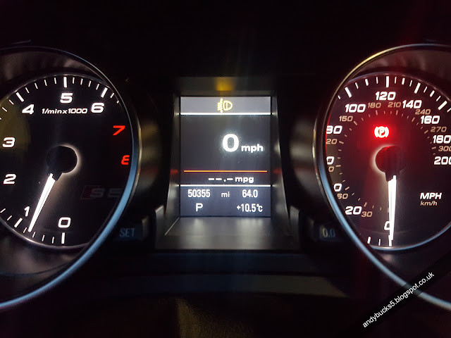
- Warning Lights: The most common symptom is the illumination of the ABS, ESP, or traction control warning lights on the dashboard.
- Reduced Performance: The vehicle’s ESP or ABS may be disabled, leading to reduced stability and braking performance, especially in adverse conditions.
- Erratic Braking: The driver might experience unusual or inconsistent braking behavior.
- No Obvious Symptoms: In some cases, there may be no noticeable symptoms other than the presence of the code.
- Check Engine Light (CEL): Although less common, the check engine light might also illuminate, depending on the specific vehicle and the severity of the issue.
2. Potential Causes Behind the P2000 Code
The P2000 code can arise from several underlying issues. Identifying the root cause is crucial for effective repair.
2.1 Faulty Wheel Speed Sensors
Wheel speed sensors are vital for monitoring the speed of each wheel and providing data to the ABS and ESP systems. If one or more of these sensors are faulty, the data transmitted can be inaccurate or implausible, triggering the P2000 code. Common issues include:
- Physical Damage: Sensors can be damaged by road debris or during maintenance.
- Wiring Issues: Damaged or corroded wiring can disrupt the sensor’s signal.
- Sensor Failure: The sensor itself may fail due to wear and tear or internal defects.
- Loose Connections: A loose connection can lead to intermittent signal loss.
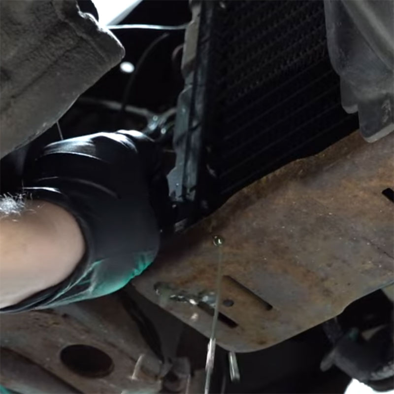
Alt text: Close-up of a wheel speed sensor installed on a Mercedes-Benz vehicle, highlighting the sensor and its connection to the wheel hub.
2.2 ESP (Electronic Stability Program) Module Issues
The ESP module processes data from various sensors and controls the braking force applied to individual wheels. Problems with this module can lead to the P2000 code. Potential causes include:
- Internal Failure: The module itself may fail due to electrical or component issues.
- Software Corruption: Corrupted software can cause the module to misinterpret data or malfunction.
- Power Supply Problems: Insufficient or unstable power supply can affect the module’s operation.
2.3 CAN Bus Communication Problems
Since the P2000 code specifically mentions the CAN bus, communication issues within this network are a prime suspect. Common problems include:
- Wiring Damage: Damaged, corroded, or shorted CAN bus wires can disrupt communication.
- Connector Issues: Loose or corroded connectors can prevent proper data transmission.
- Module Failure: A malfunctioning module on the CAN bus can interfere with communication.
- Bus Overload: Too much data traffic on the bus can lead to communication errors.
2.4 Brake System Malfunctions
Although less direct, issues within the brake system itself can sometimes trigger the P2000 code. These might include:
- Brake Pad Wear: Excessively worn brake pads can affect braking performance and sensor readings.
- Hydraulic Issues: Problems with the brake master cylinder, brake lines, or calipers can cause inconsistencies in braking torque.
- Air in the System: Air in the brake lines can lead to erratic braking and sensor readings.
2.5 Software and Programming Glitches
In modern vehicles, software glitches can cause a wide range of issues, including the P2000 code. These may include:
- Software Bugs: Errors in the vehicle’s software can cause misinterpretation of sensor data.
- Programming Errors: Incorrect programming of the ESP module or other related systems can lead to communication problems.
- Incompatible Software Versions: Conflicts between different software versions can cause errors.
3. Diagnostic Steps for the P2000 Mercedes Code
Diagnosing the P2000 code requires a systematic approach to identify the root cause. Here are the recommended steps:
3.1 Initial Scan and Code Verification
- Connect a Scan Tool: Use a Mercedes-specific scan tool to read and verify the P2000 code. Generic scan tools may not provide enough detail.
- Record All Codes: Note down all diagnostic trouble codes, not just the P2000 code. Other codes can provide valuable clues.
- Clear Codes and Retest: Clear all the codes and then take the vehicle for a test drive to see if the P2000 code returns. This helps confirm that the code is active and not a stored historical error.
3.2 Inspecting Wheel Speed Sensors
- Visual Inspection: Check each wheel speed sensor for physical damage, such as cracks, breaks, or corrosion.
- Wiring Inspection: Examine the wiring and connectors associated with each sensor. Look for damaged, frayed, or corroded wires. Pay close attention to areas where the wiring may rub against the suspension or other components.
- Resistance Test: Use a multimeter to measure the resistance of each sensor. Compare the readings to the manufacturer’s specifications. An open circuit or a significant deviation from the specified resistance indicates a faulty sensor.
- Signal Test: Use an oscilloscope to monitor the signal output from each sensor while the wheel is rotating. A faulty sensor may produce a weak, erratic, or non-existent signal.
Alt text: A technician using a multimeter to test the resistance of a wheel speed sensor on a Mercedes-Benz vehicle.
3.3 Checking the ESP Module
- Visual Inspection: Check the ESP module for any signs of physical damage or corrosion.
- Power and Ground Checks: Verify that the module is receiving proper power and ground. Use a multimeter to check the voltage at the power and ground terminals.
- Communication Test: Use a Mercedes-specific scan tool to communicate with the ESP module. If the scan tool cannot establish communication, there may be an issue with the module itself or the CAN bus wiring.
- Software Version Check: Use the scan tool to check the software version of the ESP module. Ensure that the software is up-to-date and compatible with the vehicle.
3.4 CAN Bus Diagnostics
- Visual Inspection: Inspect the CAN bus wiring for any signs of damage, corrosion, or shorts. Pay close attention to areas where the wiring may be exposed to heat, vibration, or moisture.
- Resistance Test: Use a multimeter to measure the resistance of the CAN bus wires. The resistance should be within the manufacturer’s specified range. An open circuit, short circuit, or excessive resistance indicates a problem with the wiring.
- Voltage Test: Use a multimeter to measure the voltage on the CAN bus wires. The voltage should be within the manufacturer’s specified range. A low or high voltage indicates a problem with the wiring or a connected module.
- Oscilloscope Testing: Use an oscilloscope to monitor the data signals on the CAN bus wires. The signals should be clean and consistent. Distorted or missing signals indicate a problem with the wiring or a connected module.
3.5 Brake System Evaluation
- Visual Inspection: Inspect the brake pads, rotors, calipers, and brake lines for any signs of wear, damage, or leaks.
- Brake Fluid Level and Condition: Check the brake fluid level and condition. Low brake fluid or contaminated fluid can affect braking performance.
- Brake Bleeding: Bleed the brake system to remove any air that may be trapped in the brake lines.
- Brake Pedal Travel: Check the brake pedal travel. Excessive travel or a spongy feel indicates a problem with the brake system.
4. Advanced Diagnostic Techniques
For complex cases, advanced diagnostic techniques can help pinpoint the exact cause of the P2000 code.
A Mercedes-specific scan tool provides access to detailed diagnostic information and functions that are not available with generic scan tools. These tools can perform:
- Module-Specific Diagnostics: Access detailed diagnostic information for the ESP module, ABS module, and other related systems.
- Actuator Tests: Perform actuator tests to verify the operation of individual components, such as the ABS pump and solenoids.
- Programming and Calibration: Program and calibrate the ESP module and other related systems.
- Software Updates: Update the software of the ESP module and other related systems to the latest version.
4.2 Live Data Analysis
Live data analysis involves monitoring the real-time data from various sensors and modules while the vehicle is in operation. This can help identify:
- Inconsistent Sensor Readings: Identify sensors that are providing inaccurate or inconsistent data.
- Communication Errors: Detect communication errors between modules on the CAN bus.
- Actuator Malfunctions: Identify actuators that are not functioning properly.
- Intermittent Problems: Capture intermittent problems that may not be apparent during static testing.
4.3 Oscilloscope Testing
An oscilloscope can be used to analyze the electrical signals from sensors and modules. This can help identify:
- Signal Distortion: Detect distorted or noisy signals that may be caused by wiring problems or faulty components.
- Signal Timing Issues: Identify timing issues with the signals from sensors or modules.
- Intermittent Signal Loss: Capture intermittent signal loss that may be difficult to detect with a multimeter.
4.4 Module Testing and Simulation
In some cases, it may be necessary to test the ESP module or other related modules outside of the vehicle. This can be done using a module tester or simulator. These devices can:
- Simulate Sensor Inputs: Simulate the inputs from various sensors to test the module’s response.
- Test Module Outputs: Test the module’s outputs to verify that it is controlling the actuators properly.
- Identify Internal Faults: Identify internal faults within the module that may not be apparent during in-vehicle testing.
5. Repair and Resolution Strategies
Once the root cause of the P2000 code has been identified, the appropriate repair strategy can be implemented.
5.1 Replacing Faulty Components
If a wheel speed sensor, ESP module, or other component is found to be faulty, it should be replaced with a new or remanufactured part. Follow these guidelines:
- Use OEM or High-Quality Aftermarket Parts: Use genuine Mercedes-Benz parts or high-quality aftermarket parts that meet or exceed OEM specifications.
- Proper Installation: Ensure that the replacement part is installed correctly, following the manufacturer’s instructions.
- Calibration and Programming: Calibrate and program the replacement part as needed, using a Mercedes-specific scan tool.
5.2 Wiring and Connector Repairs
If the P2000 code is caused by wiring or connector problems, the following repairs may be necessary:
- Wire Repair: Repair damaged wires by splicing in new sections of wire. Use proper crimping and soldering techniques to ensure a secure connection.
- Connector Replacement: Replace damaged or corroded connectors with new connectors.
- Wiring Harness Repair: Repair or replace damaged wiring harnesses.
- Grounding Point Repair: Clean and repair corroded grounding points.
Alt text: A technician repairing damaged wiring on a Mercedes-Benz vehicle, showing the use of proper splicing and soldering techniques.
5.3 ESP Module Programming and Calibration
If the ESP module has been replaced or reprogrammed, it may need to be calibrated to ensure proper operation. Calibration involves:
- Basic Settings Adjustment: Adjusting the basic settings of the module to match the vehicle’s specifications.
- Sensor Calibration: Calibrating the sensors that provide data to the module, such as the wheel speed sensors and steering angle sensor.
- Road Testing: Performing a road test to verify that the module is functioning properly.
5.4 CAN Bus Repair Techniques
Repairing CAN bus issues requires careful attention to detail. Common techniques include:
- Wiring Repair: Repairing damaged CAN bus wires by splicing in new sections of wire.
- Connector Replacement: Replacing damaged or corroded CAN bus connectors.
- Shielding Repair: Repairing or replacing damaged shielding on the CAN bus wires.
- Module Isolation: Isolating malfunctioning modules that are interfering with CAN bus communication.
5.5 Brake System Repairs
If the P2000 code is related to brake system malfunctions, the following repairs may be necessary:
- Brake Pad Replacement: Replacing worn brake pads.
- Rotor Resurfacing or Replacement: Resurfacing or replacing worn or damaged rotors.
- Caliper Repair or Replacement: Repairing or replacing malfunctioning brake calipers.
- Brake Line Repair or Replacement: Repairing or replacing damaged brake lines.
- Brake Bleeding: Bleeding the brake system to remove air.
6. Preventative Measures
To prevent the P2000 code from recurring, consider these preventative measures:
6.1 Regular Brake System Maintenance
- Brake Inspections: Regularly inspect the brake system for wear, damage, and leaks.
- Brake Fluid Flushes: Flush the brake fluid every two years to remove contaminants and moisture.
- Brake Pad Replacement: Replace brake pads before they become excessively worn.
- Rotor Resurfacing or Replacement: Resurface or replace rotors as needed.
6.2 Wheel Speed Sensor Care
- Sensor Inspections: Regularly inspect the wheel speed sensors for damage and corrosion.
- Wiring Inspections: Inspect the wiring and connectors associated with the sensors for damage and corrosion.
- Sensor Cleaning: Clean the sensors as needed to remove dirt and debris.
6.3 CAN Bus System Inspections
- Wiring Inspections: Regularly inspect the CAN bus wiring for damage and corrosion.
- Connector Inspections: Inspect the connectors for damage and corrosion.
- Module Diagnostics: Perform regular diagnostics on the modules connected to the CAN bus to identify potential problems early.
6.4 Software Updates
- Module Updates: Keep the software of the ESP module and other related systems up-to-date with the latest versions.
- Software Compatibility: Ensure that all software versions are compatible with each other.
7. Common Mistakes to Avoid
When diagnosing and repairing the P2000 code, avoid these common mistakes:
7.1 Neglecting Basic Checks
- Skipping Visual Inspections: Always start with a thorough visual inspection of the wiring, connectors, and components.
- Ignoring Other Codes: Pay attention to all diagnostic trouble codes, not just the P2000 code.
- Failing to Verify the Code: Always verify that the code is active and not a stored historical error.
7.2 Overlooking Wiring Issues
- Ignoring Wiring Damage: Do not overlook damaged, frayed, or corroded wires.
- Neglecting Connector Issues: Do not neglect loose or corroded connectors.
- Failing to Test Wiring: Always test the wiring for continuity, resistance, and shorts.
7.3 Ignoring Software Updates
- Failing to Check Software Versions: Always check the software versions of the ESP module and other related systems.
- Ignoring Software Updates: Do not ignore software updates that may address known issues or improve performance.
- Installing Incompatible Software: Avoid installing incompatible software versions that may cause problems.
7.4 Improper Module Replacement
- Using Low-Quality Parts: Avoid using low-quality or counterfeit parts.
- Failing to Program or Calibrate: Always program and calibrate the replacement module as needed.
- Incorrect Installation: Ensure that the replacement module is installed correctly.
8. Case Studies
Here are a few case studies illustrating how the P2000 code can be diagnosed and repaired:
8.1 Case Study 1: Wheel Speed Sensor Failure
- Vehicle: 2015 Mercedes-Benz C300
- Symptoms: ABS and ESP warning lights illuminated, P2000 code present.
- Diagnosis: Visual inspection revealed a damaged wheel speed sensor on the front left wheel. Resistance testing confirmed that the sensor was faulty.
- Repair: The faulty wheel speed sensor was replaced with a new OEM sensor. The code was cleared, and the system was tested to ensure proper operation.
- Outcome: The warning lights were extinguished, and the vehicle’s ABS and ESP systems functioned normally.
8.2 Case Study 2: ESP Module Communication Error
- Vehicle: 2017 Mercedes-Benz E350
- Symptoms: ABS and ESP warning lights illuminated, P2000 code present, along with other CAN bus communication errors.
- Diagnosis: CAN bus diagnostics revealed a communication error with the ESP module. Further testing showed that the ESP module was not responding to communication requests.
- Repair: The ESP module was replaced with a new OEM module. The module was programmed and calibrated using a Mercedes-specific scan tool.
- Outcome: The warning lights were extinguished, and the vehicle’s ABS and ESP systems functioned normally. The CAN bus communication errors were resolved.
8.3 Case Study 3: CAN Bus Wiring Damage
- Vehicle: 2019 Mercedes-Benz GLC300
- Symptoms: ABS and ESP warning lights illuminated, P2000 code present, along with intermittent communication errors.
- Diagnosis: Visual inspection of the CAN bus wiring revealed damage to the wiring harness near the engine compartment. Resistance testing confirmed a break in one of the CAN bus wires.
- Repair: The damaged wiring harness was repaired by splicing in a new section of wire. The code was cleared, and the system was tested to ensure proper operation.
- Outcome: The warning lights were extinguished, and the vehicle’s ABS and ESP systems functioned normally. The intermittent communication errors were resolved.
AutoExplain.com offers expert assistance in diagnosing and resolving the P2000 code, along with a wide range of other automotive diagnostic and repair services.
9.1 Remote Diagnostics Services
AutoExplain.com provides remote diagnostics services to help technicians and vehicle owners identify the root cause of the P2000 code. Our services include:
- Code Analysis: Analyzing the diagnostic trouble codes to identify potential causes.
- Live Data Analysis: Monitoring live data from sensors and modules to identify inconsistent readings and communication errors.
- Wiring Diagram Assistance: Providing wiring diagrams to help trace and troubleshoot wiring problems.
- Expert Guidance: Offering expert guidance and advice on diagnostic procedures and repair strategies.
Alt text: A technician using AutoExplain’s remote diagnostics service on a laptop, showing live data analysis and expert guidance.
9.2 Software Solutions and Programming
AutoExplain.com offers software solutions and programming services to address software-related issues that may be causing the P2000 code. Our services include:
- Module Programming: Programming and calibrating ESP modules and other related modules.
- Software Updates: Updating the software of the ESP module and other related systems to the latest version.
- Software Bug Fixes: Identifying and resolving software bugs that may be causing the P2000 code.
9.3 Expert Support and Guidance
AutoExplain.com provides expert support and guidance to help technicians and vehicle owners resolve the P2000 code. Our team of experienced automotive technicians and engineers can provide:
- Step-by-Step Instructions: Providing step-by-step instructions on diagnostic and repair procedures.
- Technical Documentation: Providing access to technical documentation, wiring diagrams, and repair manuals.
- Troubleshooting Assistance: Offering troubleshooting assistance to help resolve complex diagnostic and repair issues.
Having the right tools and equipment is crucial for accurately diagnosing and repairing the P2000 Mercedes Code. Here’s a list of recommended tools:
- Mercedes-Specific Scan Tool: Essential for accessing detailed diagnostic information and performing module-specific tests (e.g., Autel MaxiSYS, iCarsoft MB II).
- OBD-II Scanner: For reading and clearing generic OBD-II codes.
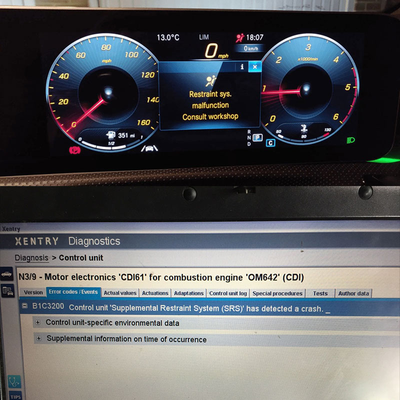
- Diagnostic Software: Mercedes-Benz XENTRY/DAS for advanced diagnostics and programming.
10.2 Multimeters and Electrical Testers
- Digital Multimeter: For measuring voltage, resistance, and current.
- Test Lights: For quick checks of circuit continuity.
- Continuity Tester: To verify the integrity of electrical connections.
10.3 Oscilloscopes
- Automotive Oscilloscope: To analyze the waveform patterns of wheel speed sensors and CAN bus signals (e.g., PicoScope, Snap-on MODIS).
- Wheel Speed Sensor Socket: For removing and installing wheel speed sensors without damaging them.
- Bearing Puller: For removing wheel hubs to access the sensors if needed.
11. Understanding Mercedes-Benz Diagnostic Systems
To effectively diagnose the P2000 code, it’s important to understand Mercedes-Benz’s diagnostic systems.
Mercedes-Benz uses advanced diagnostic tools like XENTRY/DAS (Diagnostic Assistance System) for in-depth vehicle analysis. These tools offer:
- Comprehensive System Scanning: Scanning all vehicle systems for faults.
- Real-Time Data Monitoring: Monitoring live sensor data.
- Actuation Tests: Testing individual components.
- Module Programming: Programming and calibrating control units.
11.2 Key Diagnostic Features in Mercedes Vehicles
- Self-Diagnostic Capabilities: Mercedes-Benz vehicles have self-diagnostic features that can detect and store fault codes.
- Diagnostic Trouble Codes (DTCs): Standardized codes that indicate specific faults in the system.
- Data Logging: Recording sensor data for later analysis.
- Understanding the Menu Structure: Familiarize yourself with the menu options in the diagnostic tool.
- Accessing Fault Codes: Learn how to retrieve and interpret fault codes.
- Performing Tests and Calibrations: Understand the procedures for running tests and calibrations.
12. Resources for Mercedes-Benz Technicians
Staying updated with the latest information and techniques is essential for Mercedes-Benz technicians.
12.1 Online Forums and Communities
- MBWorld Forums: A popular online community for Mercedes-Benz enthusiasts and technicians.
- BenzWorld: Another active forum with discussions on Mercedes-Benz diagnostics and repairs.
12.2 Technical Documentation and Manuals
- Mercedes-Benz WIS (Workshop Information System): Provides detailed repair procedures and technical information.
- ALLDATA: A comprehensive database with OEM service information.
12.3 Training Programs and Certifications
- Mercedes-Benz Training Academy: Offers specialized training programs for technicians.
- ASE Certifications: Automotive Service Excellence certifications to validate your skills.
13. The Future of Automotive Diagnostics with AutoExplain.com
AutoExplain.com is committed to staying at the forefront of automotive diagnostics by embracing new technologies and techniques.
13.1 Innovations in Remote Diagnostics
- Enhanced Remote Tools: Advanced diagnostic tools that can access vehicle systems remotely.
- AI-Powered Diagnostics: Using artificial intelligence to analyze data and provide diagnostic recommendations.
13.2 The Role of AI in Automotive Repair
- Predictive Maintenance: AI algorithms can analyze vehicle data to predict potential failures.
- Automated Diagnostics: AI can assist technicians in diagnosing complex issues.
13.3 Staying Ahead with AutoExplain.com
- Continuous Learning: AutoExplain.com provides ongoing training and resources to keep technicians updated.
- Embracing New Technologies: We adopt the latest diagnostic tools and techniques to ensure accurate and efficient repairs.
14. Frequently Asked Questions (FAQ)
Q1: What does the P2000 code mean on a Mercedes-Benz?
A: The P2000 code indicates that the braking torque value sent from the traction system via the CAN bus is implausible.
Q2: What are the common causes of the P2000 code?
A: Common causes include faulty wheel speed sensors, ESP module issues, CAN bus communication problems, and brake system malfunctions.
Q3: Can a generic OBD-II scanner diagnose the P2000 code?
A: A generic scanner can read the code, but a Mercedes-specific scan tool is needed for detailed diagnostics.
Q4: How do I check wheel speed sensors?
A: Inspect them for damage, check the wiring, and use a multimeter to test resistance and an oscilloscope to monitor the signal.
Q5: What is the role of the ESP module in the P2000 code?
A: The ESP module processes sensor data and controls braking force. Issues with this module can trigger the P2000 code.
Q6: How can I diagnose CAN bus communication problems?
A: Inspect the wiring, test resistance and voltage, and use an oscilloscope to monitor data signals.
Q7: What are the symptoms of a faulty ESP module?
A: Symptoms include ABS and ESP warning lights, reduced performance, and erratic braking.
Q8: Can software issues cause the P2000 code?
A: Yes, software bugs, programming errors, and incompatible software versions can cause the code.
Q9: What should I do after replacing a faulty component?
A: Calibrate and program the replacement part using a Mercedes-specific scan tool.
**Q10: How can