How to Fix C1410 Mercedes Fault Code
Experiencing the dreaded C1410 Mercedes fault code related to your Electronic Stability Program? Don’t worry, autoexplain is here to illuminate the path to a smooth and effective repair. This comprehensive guide provides you with a clear, step-by-step strategy, utilizing Mercedes-specific tools and knowledge, to confidently address this ESP system concern and restore your vehicle’s optimal performance. Delve into the intricacies of traction control valve issues and lateral acceleration sensor malfunctions with our expertly synthesized information.
Table of Contents
Toggle1. Decoding the Mercedes C1410 Diagnostic Trouble Code
The Mercedes C1410 diagnostic trouble code signifies a problem within the Electronic Stability Program (ESP) system. Specifically, this trouble code often points towards a malfunction in either the traction control valve circuit, particularly on the left-front wheel, or an issue with the lateral acceleration sensor, also known as the gyroscope. Understanding the precise meaning of this Mercedes Benz C1410 code is the crucial first step in any effective repair process. Addressing a chassis code C1410 promptly ensures the continued safety and stability of your Mercedes-Benz.
2. Root Causes of the C1410 Mercedes Error Code
Several factors can contribute to the triggering of the Mercedes C1410 error. Pinpointing the exact cause is essential for a lasting solution. Common culprits include:
-
Malfunction in the Left-Front Traction Control Valve: This valve plays a vital role in regulating braking force to individual wheels to maintain traction and stability. A fault within the valve itself can lead to the C1410 fault.
-
Wiring Issues Affecting the Traction Control Valve: Damaged, corroded, or loose wiring connecting the ESP control unit to the left-front traction control valve can disrupt the electrical circuit and trigger the Mercedes fault C1410. Rodent damage, particularly in the left-front wheel arch area, is a frequent offender.
-
Failure of the Lateral Acceleration Sensor (Gyroscope): This sensor provides critical information to the ESP system about the vehicle’s lateral movement. Inaccurate or absent data due to a faulty sensor can lead to the C1410 diagnostic code.
-
Communication Problems: Although less common for a direct C1410 code, underlying issues with the Controller Area Network (CAN) bus communication can sometimes manifest as ESP-related faults.
-
Low Battery Voltage: Insufficient battery voltage can sometimes cause various electronic control units, including the ESP module, to function improperly and potentially set false fault codes. A battery voltage below 12.4V is a potential concern.
-
Improper Brake Bleeding: In some instances, particularly in models post-2015 with specific ESP software versions (HW20+), the C1410 error code may appear after an incorrect brake bleeding procedure. This can occur if the STAR-guided ABS pump activation is not followed.
3. Symptoms Associated with the Mercedes C1410 Code
Identifying the symptoms your Mercedes-Benz is exhibiting can provide valuable clues in diagnosing the C1410 trouble code:
-
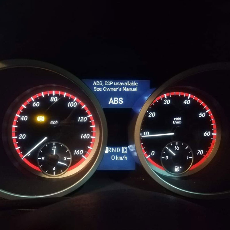
Illumination of the ESP Warning Light: This is the most common and direct indication of an ESP system malfunction. The “ESP Defective” message may also appear on the instrument cluster display.
-
Intermittent Warnings: Some users report that the ESP warning may appear and disappear sporadically during driving, only to return later.
-
Reduced ESP Functionality: You might notice a decrease in the effectiveness of the Electronic Stability Program during challenging driving conditions, such as slippery surfaces or sharp turns.
-
ABS Warning Light May Also Illuminate: In some cases, a fault within the ESP system can also affect the Anti-lock Braking System (ABS), leading to the ABS warning light turning on.
-
Potential for Other Warning Lights: Depending on the specific model and the nature of the underlying issue, other warning lights related to braking or vehicle stability might also be illuminated.
4. Diagnostic Protocol for the C1410 Mercedes DTC
4.1. Required Tools
- Diagnostic software: Xentry Openshell or Xentry Passthru
- Diagnostic Tool: Mercedes C4/C5/C6 Scanner Tools
4.2. Step By Step Guide to Diagnosis the Error
To accurately diagnose the Mercedes C1410 diagnostic trouble code, a systematic approach using the appropriate tools is essential. Here’s a detailed diagnostic protocol:
Step 1: Initial System Scan with Mercedes STAR/Xentry Diagnostics
-
Connect your Mercedes C4/C5/C6 diagnostic tool to the vehicle’s OBD-II port.
-
Perform a “Quick Test” to identify all stored fault codes in the vehicle’s systems.
-
Prioritize Codes: Pay close attention to any other codes present, especially C1036 (CAN communication fault) or C1172 (steering angle sensor fault), as these may provide additional context. Addressing these primary communication or sensor issues might resolve the C1410 indirectly.
Step 2: Live Data Analysis with STAR/Xentry
Access the live data streams for the ESP control module using STAR/Xentry. Monitor the following parameters carefully:
-
Lateral Acceleration Sensor Values: With the vehicle at rest on a level surface, the expected value should be within ±0.05g. During turns, the value should fluctuate appropriately, typically reaching up to ±1.5g. Sudden freezes or erratic readings indicate a potential sensor fault.
-
Traction Control Valve PWM Signal (Left-Front): Observe the Pulse Width Modulation (PWM) signal being sent to the left-front traction control valve. The frequency should typically range between 200 and 1000 Hz. Abnormal or absent signals can point to valve or wiring issues.
-
Wheel Speed Sensors: Compare the readings from all four wheel speed sensors while driving at a consistent speed. Discrepancies greater than 3 km/h between any of the sensors can indicate a problem with a sensor or its associated wiring, potentially influencing ESP function.
Step 3: Component Testing
-
Lateral Acceleration Sensor Testing:
-
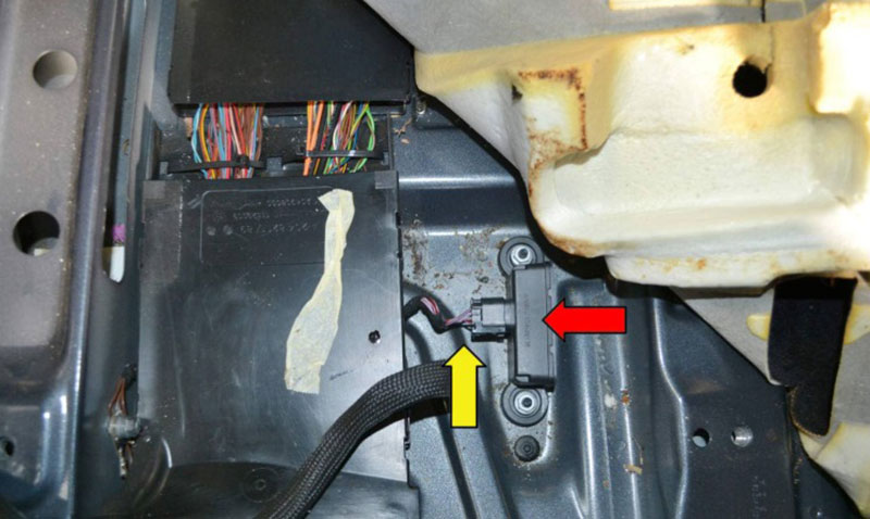
Location: The lateral acceleration sensor is typically located under the rear seats or in the trunk floor, depending on the vehicle model.
-
Resistance Test: Once located and the connector is carefully disconnected, use a multimeter to measure the resistance across the specified terminals (refer to the vehicle’s service manual for exact pinout). A typical resistance value at 20°C is between 1.2 and 1.8 kΩ. Deviations from this range suggest a faulty sensor.
-
Live Data Check (Revisited): As mentioned earlier, observing the live data for sudden freezes in the lateral acceleration sensor reading is a strong indicator of sensor failure.
-
-
Traction Control Valve Testing (Left-Front):
-
Resistance Test: With the ignition OFF and the connector to the left-front traction control valve disconnected, use a multimeter to measure the resistance across its terminals. A normal resistance value at 20°C is typically between 3.5 and 4.2Ω. An open circuit or a significantly different resistance reading indicates a faulty valve.
-
Voltage Check: With the ignition ON and the connector still disconnected, use a multimeter to check for voltage at the power supply pins of the connector. You should typically see approximately 12V. The absence of voltage suggests a wiring issue upstream of the valve.
-
-
Wiring Harness Inspection:
-
Thoroughly inspect the wiring harness associated with the left-front traction control valve, paying particular attention to the area around the left-front wheel arch, as this is a common location for rodent damage. Look for any signs of frayed insulation, cuts, or corrosion.
-
Carefully examine the connectors at the ESP control module and the traction control valve itself. Ensure they are clean, securely connected, and free from corrosion. Consider using a contact cleaner like Kontakt 60 spray to improve electrical connections.
-
Step 4: ESP Module Communication Check
-
CAN Bus Resistance Test: With the ignition OFF, use a multimeter to measure the resistance between pins 6 (CAN High) and 14 (CAN Low) of the OBD-II connector. A normal resistance value is approximately 60Ω, indicating the correct termination of the CAN bus. Deviations from this value can suggest a problem with CAN communication affecting the ESP module.
Step 5: Control Unit Reset (Proceed with Caution)
If no obvious component or wiring faults are found, a temporary reset of the ESP control unit may resolve intermittent issues. However, it’s crucial to understand that this is not a permanent fix for underlying hardware problems.
-
Switch off the ignition and wait for at least 10 minutes to allow the vehicle’s electronic systems to fully power down.
-
Disconnect the battery’s ground (negative) cable and wait for approximately 2 minutes.
-
Reconnect the battery’s ground cable securely.
-
Using STAR/Xentry, clear all stored fault codes from the ESP control module.
5. Detailed Repair Procedures for Mercedes C1410
Based on the diagnostic findings, the following repair procedures may be necessary:
5.1. Lateral Acceleration Sensor Replacement
-
Part Number Example (W203/W209): A0009056802
-
Procedure:
-
Carefully remove the rear seat or trunk trim panels to gain access to the lateral acceleration sensor’s location. Consult the vehicle’s repair manual for specific instructions.
-
Disconnect the electrical connector from the sensor.
-
Remove the bolts or fasteners securing the sensor.
-
Install the new lateral acceleration sensor, ensuring it is securely mounted in the correct orientation.
-
Reconnect the electrical connector.
-
Calibration: After replacing the sensor, calibration is crucial for accurate readings. Use STAR/Xentry to perform the calibration procedure, which typically involves driving the vehicle in figure-8 patterns at a speed of 15–25 km/h for approximately 10 minutes.
-
Verify the calibration by checking the live data in STAR/Xentry. The lateral acceleration sensor value should read approximately ±0.05g with the vehicle at rest on a level surface.
-
5.2. Traction Control Valve Service (Left-Front)
-
Part Number Example: A0044204425
-
Replacement Steps:
-
For safety, disable the ESP system via the dashboard switch if possible.
-
Carefully disconnect the electrical connector from the left-front traction control valve.
-
Loosen and disconnect the hydraulic brake lines connected to the valve. Be prepared for potential brake fluid leakage and take appropriate precautions.
-
Remove the mounting bolts securing the traction control valve to the ESP hydraulic unit.
-
Remove the old traction control valve.
-
Install the new traction control valve, ensuring the hydraulic lines are correctly aligned.
-
Tighten the mounting bolts to the specified torque (example: 22 Nm).
-
Tighten the hydraulic line fittings to the specified torque (example: 18 Nm).
-
Reconnect the electrical connector.
-
Bleed the brake system thoroughly, following Mercedes-Benz’s recommended procedure, ideally using the STAR/Xentry guided function for ABS pump activation.
-
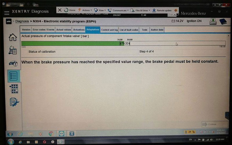
Post-Repair Calibration: Perform the “ESP Basic Settings” procedure using STAR/Xentry: Navigate to Control Units → ABS/ESP → Basic Settings → Traction Control Valve Adaptation. Follow the on-screen instructions.
-
5.3. ESP Control Module Replacement
-
Indications: This is usually considered only if the C1410 code persists after thorough testing and replacement of the lateral acceleration sensor and traction control valve, and after verifying wiring integrity.
-
Procedure Example (W203):
-
Safety First: Disconnect the vehicle’s battery.
-
In some models, access may require the removal of the steering wheel and airbag unit. Follow the manufacturer’s safety instructions meticulously when handling airbag components.
-
Locate the ESP control module, which is often integrated with the ABS hydraulic unit in the engine compartment.
-
Disconnect the electrical connectors from the ESP control module.
-
Unbolt the ESP control module from the hydraulic unit.
-
Install the new ESP control module onto the hydraulic unit and secure it with the bolts.
-
Reconnect the electrical connectors.
-
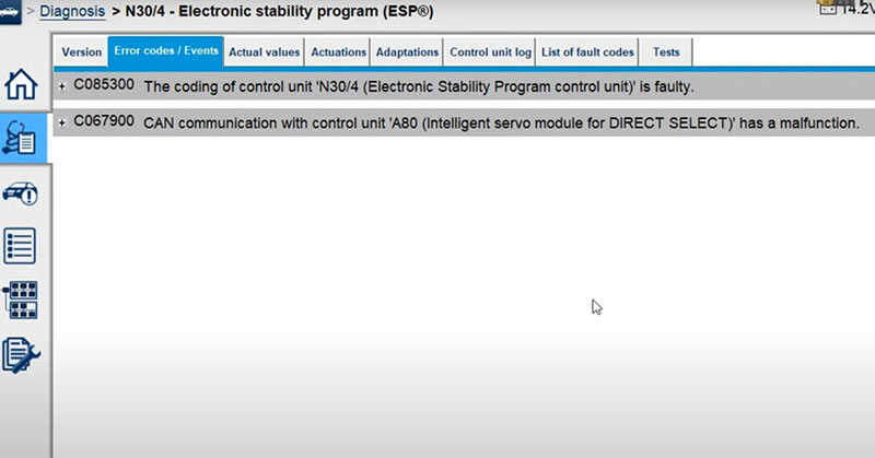
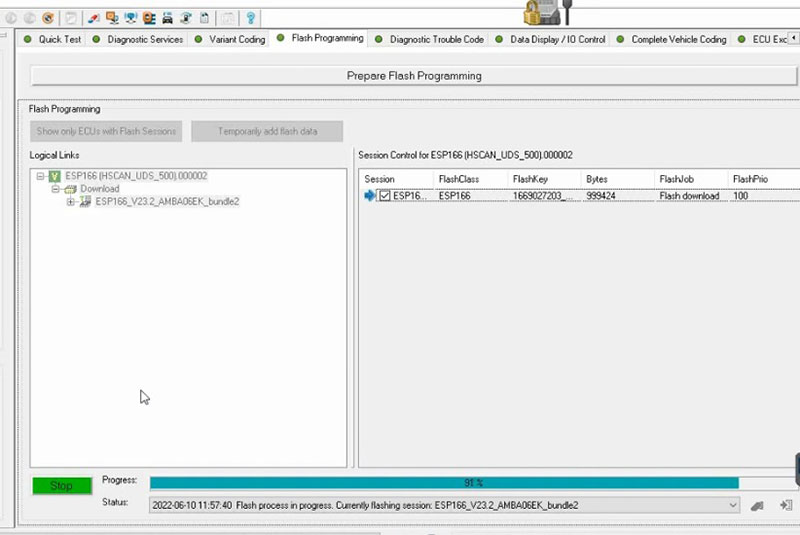
Coding: The new ESP control module will require coding and SCN (Software Calibration Number) authorization using STAR/Xentry to be properly integrated with the vehicle’s electronic systems. This step is crucial for the module to function correctly. Follow the guided coding procedures within STAR/Xentry.
-
6. Critical Post-Repair Steps for ESP System Functionality
After performing any repairs to the ESP system, these crucial steps are necessary to ensure proper operation:
-
Adaptation Drive: Perform an adaptation drive as recommended by Mercedes-Benz. This typically involves driving the vehicle at a speed between 30 and 50 km/h for approximately 10 minutes, making at least three full-lock steering turns in each direction (left and right) in a safe environment. This allows the ESP system to recalibrate its sensors and parameters.
-
System Reset: Using STAR/Xentry, navigate to the ESP control module and perform a reset of learned values: ESP Control Module → Adaptations → Reset Learned Values. This clears any previously stored adaptation data and allows the system to learn fresh values with the new or repaired components.
-
Final System Scan and Code Clearing: After the adaptation drive and system reset, perform another full system scan with STAR/Xentry and ensure that the C1410 fault code, as well as any other related codes, are no longer present.
7. Understanding Cost and Time Estimates for Repairs
Please note that these are estimated ranges and actual costs can vary depending on factors such as the specific Mercedes-Benz model, the location of the repair, and the labor rates of the service facility. When considering aftermarket sensors versus OEM parts, remember that using only OEM parts is highly recommended by autoexplain to prevent potential signal mismatches and ensure the reliability of the ESP system.
| Repair | OEM Part Cost | Estimated Labor Time |
| Lateral Acceleration Sensor | $180 – $300 | 1.5 hours |
| Traction Control Valve | $220 – $400 | 2 hours |
| ESP Module Replacement | $800 – $1,200 | 3 hours |
These estimates do not include potential diagnostic fees or the cost of brake fluid and bleeding.
8. Important Technical Notes for Troubleshooting C1410 Mercedes
-
Intermittent Faults: When dealing with intermittent ESP warnings and the C1410 code, pay close attention to the wiring, especially in the left-front wheel arch area. Look for even minor signs of frayed insulation or loose connectors. Battery voltage should also be checked under load to rule out voltage drops as a cause of temporary ESP issues.
-
Software Updates: For Mercedes-Benz models manufactured after 2015, ensure that the ESP control module has the latest software version installed (specifically HW20+ or newer) as some later models require updated software for proper traction control valve operation. Check for available software updates using STAR/Xentry.
-
False Positives: Be aware that the C1410 code can sometimes be triggered after an improper brake bleeding procedure, particularly in newer models. Always follow the STAR/Xentry guided procedure for ABS pump activation during brake bleeding to avoid this.
-
Parasitic Drain Testing: If the C1410 code persists and no obvious component faults are found, consider performing a parasitic drain test on the vehicle’s electrical system. An excessive current draw when the vehicle is off can lead to low battery voltage and potentially trigger spurious ESP faults.
Get Expert Help for Mercedes C1410 Fault Code
Resolving the C1410 Mercedes-Benz fault code requires a systematic diagnostic approach. The most effective solutions include:
- Replacing the lateral acceleration sensor or traction control valve
- Using STAR/Xentry for guided tests and calibrations
- Inspecting wiring for damage and ensuring proper module communication
If you’re experiencing persistent ESP issues, our team at AutoExplain can help! We specialize in Mercedes-Benz diagnostics, coding, and programming. Contact us today for professional support.
📲 WhatsApp: +1(936)2896695

BMW FSC Codes Explained: Full FSC Code List for F-Series
What is a Stage 3 Remap?
The Best Car Tuning Software in 2026: A Comprehensive Guide for Professionals
