Bank 1 bank 2 oxygen sensors play a crucial role in your vehicle’s performance and emissions. They constantly monitor the exhaust gases and relay this information to the engine control unit (ECU), which then adjusts the air-fuel mixture for optimal combustion. A malfunctioning oxygen sensor can lead to a variety of problems, impacting both your wallet and the environment.
For any automotive technician working on BMW, Audi, or Mercedes-Benz, understanding the layout, behavior, failure patterns, and diagnostic process for these sensors is essential. Misidentifying sensor banks or misreading fault codes can lead to wasted time, money, and comebacks.
This guide walks you through everything you need to know about Bank 1 and Bank 2 oxygen sensors — from identification to diagnostics, common DTCs, replacement tips, and brand-specific nuances.
Correctly identifying Bank 1 and Bank 2 is a foundational skill for any automotive technician working with engine performance, emissions systems, or diagnostic trouble codes (DTCs) related to oxygen sensors. Misdiagnosing the location of a sensor can lead to incorrect repairs, wasted time, and comebacks. Let’s explore this in depth.
Bank 1 is defined as the side of the engine that contains Cylinder Number 1. This is not based on vehicle orientation (driver or passenger side), but rather on the engine’s firing order and mechanical design.
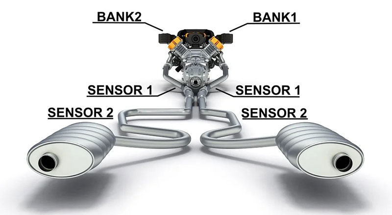
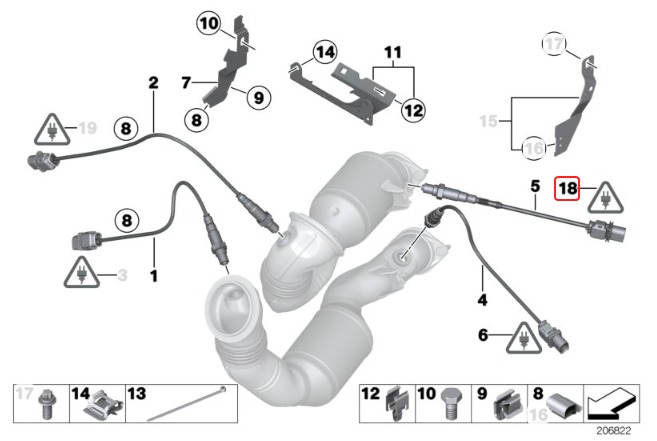
In V-shaped engines (V6, V8, V10), the cylinders are split into two banks — one on each side of the “V.”
In inline engines (I4, I6), all cylinders are in a single row, so there is only Bank 1 — no Bank 2 exists.
How to find Cylinder 1:
Consult the firing order chart or the engine service manual.
Cylinder 1 is often at the front of the engine block, but not always on the same physical side across all manufacturers.
Example:
BMW N63 V8: Cylinder 1 is on the passenger side
Mercedes M278 V8: Cylinder 1 is on the driver side
Knowing this allows you to confidently determine which side is Bank 1.
Bank 2 is simply the opposite side of Bank 1.
It hosts the remaining cylinders not in Bank 1.
For engines with equal cylinder distribution, Bank 2 typically contains the even-numbered cylinders (2, 4, 6, 8).
📌 Important for Technicians:
Never assume Bank 1 is on the driver’s side just because it “looks” like it — cylinder layout varies between left-hand and right-hand drive vehicles, and among manufacturers.
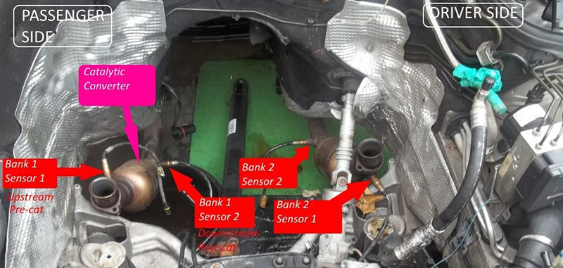
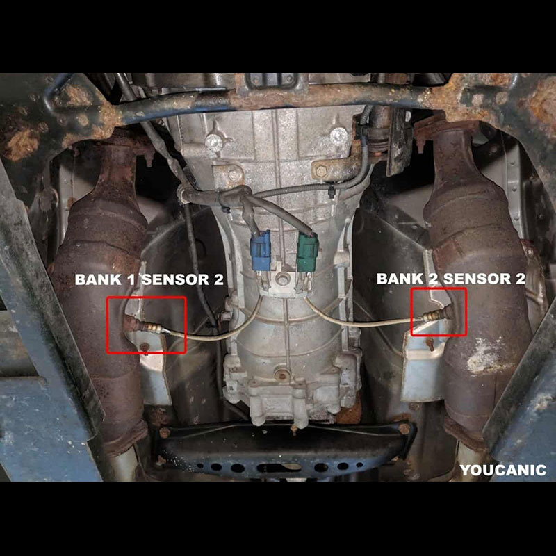
Each bank typically has two oxygen sensors:
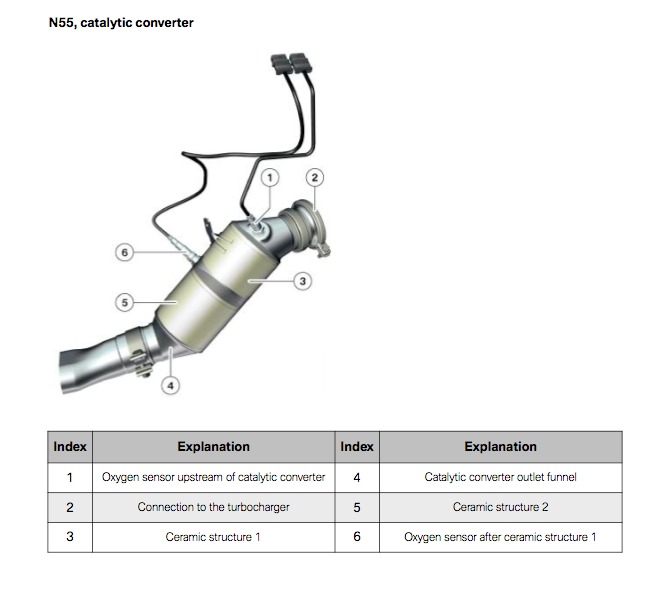
Sensor 1: Located before the catalytic converter (upstream)
Sensor 2: Located after the catalytic converter (downstream)
📋 Sensor Naming Convention:
| Sensor Name | Location | Function |
|---|---|---|
| Bank 1 Sensor 1 | Upstream on the side with Cylinder 1 | Controls air-fuel ratio (feedback loop) |
| Bank 1 Sensor 2 | Downstream on the same side | Monitors catalytic converter performance |
| Bank 2 Sensor 1 | Upstream on opposite side | Controls air-fuel ratio (for Bank 2) |
| Bank 2 Sensor 2 | Downstream on opposite side | Monitors CAT efficiency for Bank 2 |

🧠 Mnemonic Tip for Technicians:
Sensor 1 = Upstream
Sensor 2 = Downstream
Always refer to both bank and sensor position when diagnosing codes like P0150 or P0430.
If you’re unsure of the bank layout in a specific vehicle, use this step-by-step method:
Access the engine firing order diagram in the service manual or OEM database.
Locate Cylinder 1 based on that firing order.
Confirm which side of the engine block houses Cylinder 1 — this side is Bank 1.
Use an OBD2 scan tool to unplug an upstream sensor and see which DTC is triggered (e.g., P0130 = Bank 1 Sensor 1).
Visually trace the exhaust manifold routing. Typically, each bank will have its own manifold and sensors.
| Engine Model | Engine Type | Bank 1 Location | Notes |
|---|---|---|---|
| BMW N54 (135i/335i) | Inline-6 | Only Bank 1 | 2 upstream O2 sensors (wideband) but same bank |
| Audi 3.0 TFSI | V6 | Right side | Cylinder 1 on right (passenger) side |
| Mercedes M276 | V6 | Left side | Cylinder 1 near firewall on driver side |
| BMW N63 (X5 4.4i) | V8 | Right side | Twin-turbo, front-mounted CATs |
| Mercedes M278 (S550) | V8 | Left side | Left = Bank 1, right = Bank 2 |
🔧 Caution for Turbo Engines:
Some turbocharged layouts (e.g., BMW N63 or Audi S6 4.0T) may reverse the conventional sensor placement due to hot-V configuration, making service diagrams even more crucial.
| Mistake | Cause | Prevention |
|---|---|---|
| Replacing wrong sensor | Confusing driver/passenger sides | Always find Cylinder 1 first |
| Interchanging Sensor 1 and 2 | Misreading scanner data | Match DTC with exhaust routing |
| Misdiagnosing an inline engine | Believing Bank 2 exists on I4/I6 | Remember: Inline = Bank 1 only |
| Replacing sensor for CAT issue | Sensor 2 mimics Sensor 1 | Use live data to verify CAT failure |
⚠️ Real-World Tip:
In some models, the wiring harness connectors for Sensor 1 and Sensor 2 are located close together, and if mislabeled during a repair, the ECU may receive the wrong input — leading to rich/lean conditions, false P0420/P0430 codes, and driveability issues. Always mark each connector during removal and verify with wiring diagrams.
Modern engines use oxygen sensors (O2 sensors) as critical inputs to maintain optimal combustion, reduce emissions, and monitor the health of the catalytic converter. In most gasoline-powered vehicles with OBD-II systems, each engine bank typically includes two O2 sensors:
Upstream Sensor (Sensor 1) – Before the catalytic converter
Downstream Sensor (Sensor 2) – After the catalytic converter
Let’s dive into the role and behavior of each one.
2.1.1. Function:
These are the primary oxygen sensors that sit before the catalytic converters. They monitor the oxygen level in the exhaust gases directly after combustion and are critical for controlling the air-fuel ratio in real time.
Provide feedback to the ECU for closed-loop fuel control
Help maintain an ideal 14.7:1 air-fuel ratio (stoichiometric)
Constantly switch between rich (low O₂) and lean (high O₂) signals
Allow the ECU to adjust fuel injection pulse width to optimize combustion efficiency
These sensors are wideband (on newer vehicles) or narrowband (on older systems)
Voltage typically cycles between 0.1V to 0.9V (narrowband) to represent lean/rich conditions
In wideband O2 sensors, feedback is more precise and measured in current (mA) or lambda values
Poor fuel economy
Hesitation or surging
Rough idle
Check Engine Light (CEL) with codes like:
P0130 (Bank 1 Sensor 1 Circuit)
P0150 (Bank 2 Sensor 1 Circuit)
Fuel Trim DTCs (P0171/P0174 lean, P0172/P0175 rich)
2.2.1. Function:
These are located after the catalytic converters and primarily exist to monitor the efficiency of the catalytic converters, not to control fuel mixture.
Evaluate how well the catalytic converter is storing oxygen and processing exhaust gases
Compare exhaust content before and after the CAT
Send this data to the ECU, which then checks for CAT efficiency
Trigger diagnostic codes if the CAT performance falls below federal limits
Voltage signal should remain relatively stable if the CAT is working correctly
A “lazy” or switching downstream sensor indicates catalyst failure
The sensor reads less frequently than the upstream and has a flatter signal curve
Check Engine Light (CEL) with codes such as:
P0420 (Catalyst System Efficiency Below Threshold – Bank 1)
P0430 (Same – Bank 2)
Failed emissions test
False CAT failure diagnosis if sensor gives bad data
Delayed readiness monitor for oxygen or catalyst
| Sensor | Position | Controls Fuel? | Monitors Catalyst? | Typical Signal Behavior |
|---|---|---|---|---|
| Bank 1 Sensor 1 | Upstream | ✅ Yes | ❌ No | Switches quickly (rich/lean) |
| Bank 2 Sensor 1 | Upstream | ✅ Yes | ❌ No | Switches quickly (rich/lean) |
| Bank 1 Sensor 2 | Downstream | ❌ No | ✅ Yes | Flat, stable signal |
| Bank 2 Sensor 2 | Downstream | ❌ No | ✅ Yes | Flat, stable signal |
Using a scan tool or diagnostic software (like ODIS, ISTA, or XENTRY), check live data:
Upstream Sensors (Sensor 1) should switch rapidly when the engine is warm:
~0.1V (lean) to ~0.9V (rich) or lambda values close to 1.0 (wideband)
Downstream Sensors (Sensor 2) should show stable readings — if they mimic the switching of the upstream sensor, it’s often a sign the catalytic converter is failing or has been removed.
Oxygen sensors are crucial for maintaining optimal engine performance and emissions compliance. However, like any sensor exposed to extreme heat, exhaust gases, and vibration, they’re prone to failure over time. Below are the most common problems affecting Bank 1 and Bank 2 oxygen sensors, along with detailed explanations to help you diagnose like a pro.
3.1.1. Problem:
O2 sensors rely on a clean exhaust stream to accurately detect oxygen levels. Contamination from burned engine oil, coolant leaks, or fuel additives can coat the sensor’s sensing element, reducing its accuracy or response time.

3.1.2. Symptoms:
Delayed switching response
Flat voltage signals from upstream sensors
DTCs like P0133 (Slow Response) or P0153
3.1.3. Common Causes:
Valve cover gasket leaks (oil into combustion)
Internal coolant leaks (e.g. blown head gasket)
Fuel system cleaner overuse
3.1.4. Diagnosis Tip:
Use live data on a scan tool. If upstream sensor voltage is sluggish or doesn’t switch between ~0.1–0.9V (narrowband), suspect contamination. Compare both banks — if one switches slower than the other, it may be contaminated.
3.1.5. Repair Tip:
Replace the affected sensor(s).
Fix the root cause:
▸ If oil is entering the chamber, check for PCV valve failure or valve cover gasket leak.
▸ If coolant contamination is suspected, perform a cooling system pressure test to check for head gasket failure.
▸ Advise against using excessive fuel additives or octane boosters.
3.2.1. Problem:
Modern O2 sensors (especially upstream) have an integrated heater circuit to bring the sensor up to operating temperature quickly. When the heater fails, the sensor responds too slowly, causing the ECU to flag it.
3.2.2. Symptoms:
Long time to go into closed loop
Cold start roughness
Codes like P0030 (Bank 1 Sensor 1 Heater), P0050 (Bank 2 Sensor 1 Heater)
3.2.3. Common Causes:
Blown fuse or open heater wiring
Failed heater element inside the sensor
Corroded connectors
3.2.4. Diagnosis Tip:
Use a multimeter to check heater resistance (~4–10 ohms typical). You can also use a scan tool to observe if the ECU reaches “closed loop” shortly after startup. A failed heater delays this.
3.2.5. Repair Tip:
Inspect and test sensor fuses and relays.
Replace the O2 sensor if the heater resistance is out of spec.
Use OEM-grade sensors rather than cheap aftermarket ones, which often have lower heater lifespan.
Always clear the code and check live data for closed-loop status on startup after repair.
3.3.1. Problem:
All O2 sensors have a limited lifespan. Over time (typically 80,000–150,000 km), their internal zirconia element degrades, leading to inaccurate readings and sluggish response times.
3.3.2. Symptoms:
Poor fuel economy
Hesitation or flat acceleration
Intermittent lean/rich DTCs
Codes like P0130, P0150, P2195, P2197 (bias stuck lean), P2196, P2198 (bias stuck rich)
3.3.3. Common Causes:
Normal wear
High-heat exposure (turbocharged engines)
Excessive idle time (urban driving)
3.3.4. Diagnosis Tip:
Upstream sensors should switch multiple times per second. If they respond slowly or hold a biased voltage (e.g. always high or low), replacement is usually necessary.
3.3.5. Repair Tip:
Replace upstream sensors every 100,000–150,000 km (or per manufacturer’s maintenance schedule).
Always replace in pairs (Bank 1 & Bank 2) for balanced engine operation if both are old.
Use anti-seize on sensor threads (if not pre-coated) and torque to spec to avoid damaging the bung.
3.4.1. Problem:
Wiring harnesses for oxygen sensors are exposed to constant heat and vibration. Over time, insulation may crack, pins may corrode, or wires may break internally.
3.4.2. Symptoms:
Intermittent O2 sensor communication
Short to ground or open circuit faults (e.g. P0134, P0141)
No signal in live data stream
3.4.3. Common Causes:
Heat damage (especially in turbo or V8 engines)
Rodents chewing sensor wires
Incorrect installation (pinched harness)
3.4.4. Diagnosis Tip:
Perform a wiggle test on the wiring while watching live data. Use a multimeter to check continuity, especially between sensor connector and ECU. Visually inspect for burns or melting near the exhaust.
3.4.5. Repair Tip:
Visually inspect wiring near the exhaust—look for melting, cracks, or rub-through.
Test continuity from sensor plug to ECU pin.
Clean and apply dielectric grease on terminals to prevent future corrosion.
Replace damaged sections of the harness using high-temp automotive wire and weather-sealed connectors.
3.5.1. Problem:
Replacing the wrong sensor is common — especially confusing Bank 1 vs Bank 2, or Sensor 1 vs Sensor 2. This can result in unresolved DTCs even after a new sensor is installed.
3.5.2. Symptoms:
DTC returns after sensor replacement
Data readings don’t match expected sensor behavior
Fuel trim or emissions codes persist
3.5.3. Common Causes:
Misidentifying sensor location
Using universal-fit sensors with spliced wires
Wrong part number for vehicle model
3.5.4. Diagnosis Tip:
Use factory service diagrams to verify exact sensor location. Cross-reference part number on old and new sensor. Use a scan tool to observe which sensor shows live data changes when you induce a change (e.g., intentional vacuum leak or fuel enrichment).
3.5.5. Repair Tip:
Always use OEM part numbers or VIN-based parts lookup.
Label harness connectors when removing multiple sensors.
Use the factory cylinder layout guide to identify Bank 1 (cylinder 1 side) vs Bank 2.
Never rely on wire color alone — some brands use similar color codes.
3.6.1. Problem:
Leaks in the exhaust manifold or upstream of the O2 sensor can introduce extra oxygen into the exhaust stream, fooling the sensor into thinking the mixture is lean.
3.6.2. Symptoms:
Erratic fuel trim readings
Lean codes (P0171/P0174)
Poor idle or surging
3.6.3. Common Causes:
Cracked exhaust manifold
Loose manifold bolts
Failed gasket between cylinder head and exhaust
3.6.4. Diagnosis Tip:
Use a smoke machine or listen for ticking sounds on cold start. Monitor fuel trims — high long-term fuel trim values on one bank suggest a pre-sensor exhaust leak.
3.6.5. Repair Tip:
Reseal or replace exhaust manifold gaskets.
Torque down loose exhaust bolts.
Replace cracked flex pipes or flanges.
Always fix exhaust leaks before replacing O2 sensors to avoid unnecessary parts cost.
3.7.1. Problem:
Though not technically a sensor issue, a failed catalytic converter affects downstream sensor readings. The ECU may misinterpret it as a sensor failure or generate P0420/P0430 codes.

3.7.2. Symptoms:
P0420 (Bank 1 Catalyst Efficiency Below Threshold)
P0430 (Bank 2 Catalyst Efficiency)
Downstream sensor mimics upstream sensor waveform
3.7.3. Common Causes:
Long-term rich fuel conditions
Engine misfire damaging the CAT
Oil burning
3.7.4. Diagnosis Tip:
Use scan tool graphing: downstream O2 sensor should show minimal switching if the CAT is functional. If it mirrors Sensor 1, suspect a bad CAT.
3.7.5. Repair Tip:
Replace the catalytic converter if it’s internally damaged or melted.
Replace downstream sensor after CAT replacement if readings don’t normalize.
Address root cause of CAT damage (misfire, oil consumption, over-fueling) to prevent recurrence.
| Code | Description |
|---|---|
| BMW 2C9C / 2C9D | Lambda probe before catalytic converter, Bank 1 / Bank 2, signal |
| BMW 2C9E / 2C9F | Lambda probe before cat, trimming control, Bank 1 / Bank 2 |
| BMW 2CA0 / 2CA1 | Lambda probe heating, Bank 1 / Bank 2 |
| BMW 2C31 / 2C32 | Lambda probe after catalytic converter, signal |
| BMW 2C3E / 2C3F | Lambda probe after cat, heating function, Bank 1 / Bank 2 |
| BMW 29F4 / 29F5 | Catalytic converter efficiency, Bank 1 / Bank 2 |
📝 BMW often uses “2Cxx” and “2Axx” codes for oxygen and mixture adaptation faults.
| VAG Code | OBD-II Equivalent | Description |
|---|---|---|
| Audi 17584 / P1176 | P1176 | O2 Correction Behind Catalyst, Bank 1 |
| Audi 17585 / P1177 | P1177 | O2 Correction Behind Catalyst, Bank 2 |
| Audi P0139 / 16523 | P0139 | O2 Sensor Slow Response, Bank 1 Sensor 2 |
| Audi P0140 / 16524 | P0140 | O2 Sensor No Activity, Bank 1 Sensor 2 |
| Audi P1113 / 17521 | P1113 | O2 Sensor Heater Circ. Bank 1 Sensor 1 |
| Audi P1121 / 17529 | P1121 | O2 Sensor Heater Circ. Bank 2 Sensor 1 |
| Audi P0130 / 16514 | P0130 | Bank 1 Sensor 1 Malfunction |
| Audi P0154 / 16534 | P0154 | Bank 2 Sensor 1 No Activity |
🛠 Audi/VW use both P-codes and internal 5-digit DTCs like 16523 (P0139).
| MB DTC | Generic Equivalent | Description |
|---|---|---|
| Mercedes P0130 | P0130 | O2 Sensor Circuit Bank 1 Sensor 1 |
| Mercedes P0150 | P0150 | O2 Sensor Circuit Bank 2 Sensor 1 |
| Mercedes P0141 | P0141 | O2 Sensor Heater Circuit Bank 1 Sensor 2 |
| Mercedes P0161 | P0161 | O2 Sensor Heater Circuit Bank 2 Sensor 2 |
| Mercedes 0525 / 0526 | N/A | Lambda probe upstream of CAT Bank 1 / 2 – signal error |
| Mercedes 2054 / 2055 | N/A | Component B2S1 – signal too high/low |
| Mercedes 2035 / 2036 | N/A | Lambda Control Deviation Bank 1 / 2 |
| Mercedes 2713 / 2714 | N/A | Post-catalytic O2 sensor Bank 1 / 2 – heater circuit malfunction |
🔍 In Xentry or Star Diagnostic tools, the codes may appear differently and often involve “Component Bxx/Sx” for sensor mapping.
“Properly functioning oxygen sensors are vital for optimal engine performance,” says Michael Stevenson, a seasoned automotive engineer with over 20 years of experience. “Regular maintenance and timely replacement can save you money on fuel and prevent costly repairs down the road.”
Understanding bank 1 bank 2 oxygen sensors is crucial for maintaining your vehicle’s health and performance. By understanding how they work and recognizing the signs of failure, you can address potential issues promptly and keep your car running efficiently while minimizing its environmental impact. Don’t ignore those warning signs – address them head-on.
Contact AutoExplain today for expert assistance:
WhatsApp: +1(936)2896695
Email: [email protected]
Website: AutoExplain