
DTC P0236 Audi signifies a turbocharger boost sensor A circuit range/performance issue, hindering optimal engine performance. AutoExplain equips you with the knowledge to accurately diagnose, troubleshoot, and resolve this issue, ensuring your Audi runs smoothly. We’ll explore potential causes, diagnostic procedures, and effective repair strategies, and also uncover solutions for enhancing the performance of your auto repair services.
What does the DTC P0236 code really mean for your Audi?
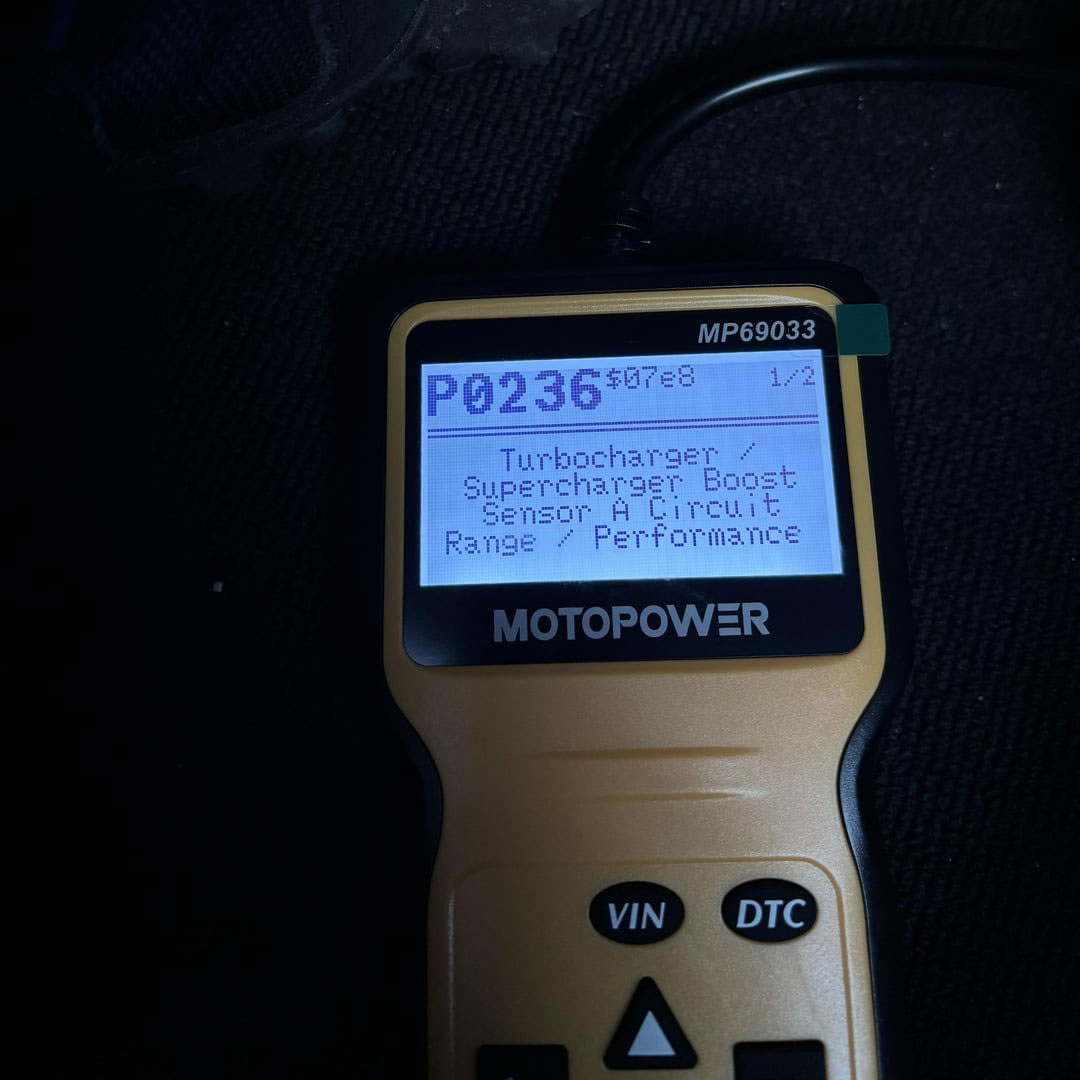
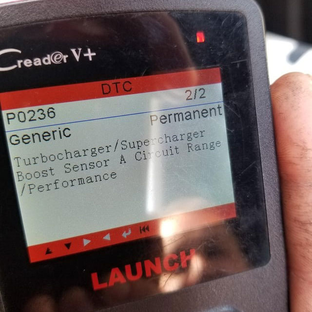
The diagnostic trouble code (DTC) P0236 indicates a problem within the turbocharger boost sensor “A” circuit range/performance. This means the engine control unit (ECU) detects that the signal from the boost sensor is either out of the expected range or not performing as it should. The turbocharger boost sensor, also known as the manifold absolute pressure (MAP) sensor, monitors the air pressure inside the intake manifold. According to a study by the ASE (Automotive Service Excellence), accurate sensor readings are crucial for the ECU to adjust fuel delivery and ignition timing, optimizing engine power and efficiency. When the P0236 code appears, it signals that the ECU isn’t receiving reliable data from the boost sensor, which can lead to a variety of drivability issues.
The P0236 fault is commonly found in:
Audi A4, A5, A6, A7
Audi Q5, Q7
Audi TT and S3/S4 models
Engines: 2.0 TFSI, 3.0 TDI, 1.8T, and others with turbochargers
This code can appear on both gasoline and diesel turbocharged engines.
What are the symptoms that can help you identify the P0236 error in your Audi?
Identifying the symptoms associated with DTC P0236 is the first step in diagnosing the problem. Here are the most common symptoms:
What causes the P0236 error to appear on your Audi?
Several factors can trigger the P0236 code in your Audi. Knowing these potential causes can help you narrow down the problem and perform targeted diagnostics:
Before jumping into repairs, make sure you have the right tools. Here’s what professionals use to diagnose audi p0236:
✅ OBD-II Diagnostic Tool (e.g., VCDS, ODIS, Autel, Launch X431)
✅ Digital Multimeter – for testing signal voltages and resistances
✅ Socket Set & Screwdrivers – for removing sensors or intake components
✅ Vacuum Pump (if testing turbo actuators)
✅ Smoke Tester – to identify vacuum or boost leaks
VCDS (VAG-COM) – for live data and actuator testing
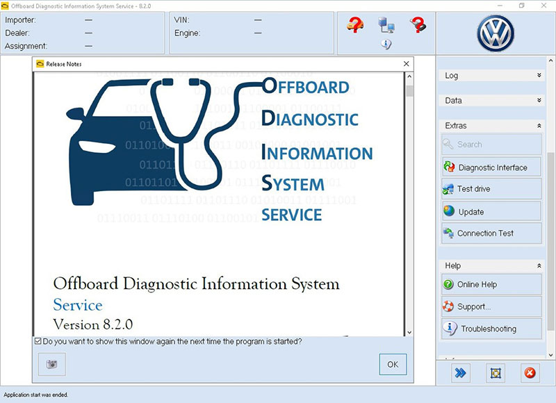
ODIS Service – official dealer-level software for Audi diagnostics and coding
Resolving the DTC P0236 on your Audi requires a systematic diagnostic approach, especially since it involves the Turbo Boost Sensor “A” Circuit Range/Performance. Follow this step-by-step process to correctly diagnose and repair the issue.
Connect a Diagnostic Scanner (VCDS, ODIS, or any Audi-compatible scanner).
Navigate to the Engine Control Module (ECM) and read the stored fault codes.
Confirm that P0236 is present. If there are other related codes (like P0299 or P0106), make note of them as they could indicate supporting faults.
Do not clear the code yet. It’s important to collect freeze frame data (RPM, throttle position, boost pressure, etc.) to understand when the fault occurred.
Related Fault Codes to P0236 Audi
| Code | Description |
|---|---|
| P0235 | Turbocharger Boost Sensor A Circuit Malfunction |
| P0237 | Turbocharger Boost Sensor A Circuit Low |
| P0238 | Turbocharger Boost Sensor A Circuit High |
| P0299 | Turbo/Super Charger Underboost Condition |
| P0243 | Turbocharger Wastegate Solenoid A Malfunction |
| P0244 | Turbocharger Wastegate Solenoid A Range/Performance |
| P2262 | Turbo Boost Pressure Not Detected – Mechanical |
| P2563 | Turbocharger Boost Control Position Sensor Circuit Range/Performance |
| P2564 | Turbocharger Boost Control Position Sensor Circuit Low |
| P2565 | Turbocharger Boost Control Position Sensor Circuit High |
| P3340 | Turbocharger Wastegate Regulator Control Circuit/Open |
| P3346 | Turbocharger Boost Control Solenoid Performance |
=> You may also like:
The Manifold Absolute Pressure (MAP) sensor, also known as the boost pressure sensor in turbocharged Audi engines, plays a critical role in engine load calculations. When it malfunctions, it can trigger DTC P0236. Here’s how to properly inspect it:
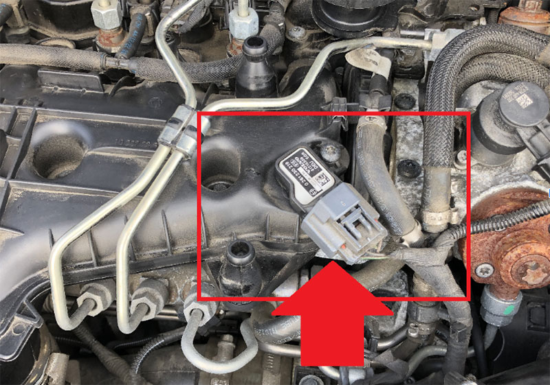
3.1.1 Locate the MAP Sensor
On most Audi engines, the MAP sensor is mounted on or near the intake manifold or intercooler piping.
Refer to your specific Audi model’s service manual for the exact location (for example, in a 2.0 TFSI engine, it’s often on the plastic intake manifold or turbo pressure pipe).
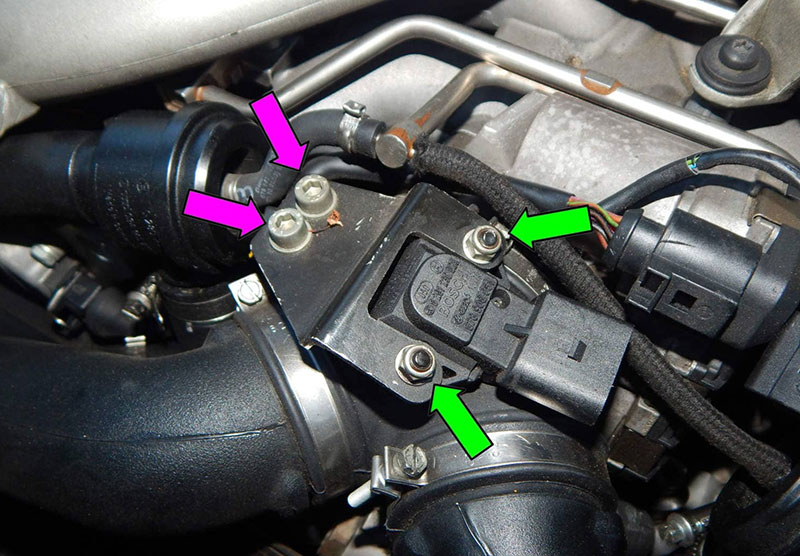
3.1.2 Visual Inspection
Carefully check the physical condition of the sensor and its surrounding area:
Look for cracked housing, oil contamination, corroded pins, or broken connectors.
Inspect the sensor harness and wiring for chafing, pinching, exposed wires, or melted insulation.
⚠️ Common Issue: Oil blow-by from the PCV system can foul the sensor diaphragm, especially on older turbocharged Audi engines.
3.1.3 Check the Electrical Connector
Unplug the sensor and check for bent, corroded, or loose terminals.
Use electrical contact cleaner and a soft brush if corrosion is present.
Gently tug each wire at the back of the connector to ensure none are internally broken.
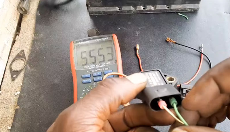
3.1.4 Test the Sensor with a Multimeter or Scan Tool
A. Using a Multimeter (for analog MAP sensors):
Turn ignition to ON (engine off).
Locate the 5V reference wire, ground, and signal wire (check wiring diagram).
Backprobe the signal wire:
At ignition ON, expect a voltage reading between 0.5 to 1.5 volts depending on ambient pressure.
When the engine is running or applying vacuum/boost manually (with a hand vacuum pump), the voltage should vary smoothly.
No change or erratic voltage = faulty sensor.
B. Using a Diagnostic Scan Tool:
Connect the tool and navigate to live data or measured values.
Monitor the boost pressure (MAP sensor) readings:
Compare live readings to ambient pressure with engine off (~100 kPa or ~14.7 psi at sea level).
With the engine running and revved, boost pressure should rise.
If values are flat, spiking, or out of expected range, the sensor may be faulty.
3.1.5 Replace the MAP Sensor if Necessary
If the sensor:
Shows no voltage or erratic readings
Has physical damage or oil intrusion
Fails continuity or resistance checks per factory specs
➡️ Then replace the sensor with a high-quality OEM or equivalent part.
Torque it to spec and ensure proper sealing (some MAP sensors use rubber O-rings or gaskets that must be intact to prevent boost leaks).
Boost leaks and intake system problems are common causes of DTC P0236 on turbocharged Audi engines. If unmetered air enters or pressurized air escapes the intake system, the ECU will detect a mismatch between boost pressure (MAP sensor) and expected turbo output, triggering this code.
Here’s how to carefully inspect the system:
3.2.1 Understand the Boost Path
Before inspecting, it’s helpful to know how the turbocharged air flows:
Turbocharger compresses air
Air goes through charge pipes and intercooler
Then into the throttle body and intake manifold
Finally reaches the cylinders
Anywhere along this path, a leak can cause pressure loss or incorrect readings.
3.2.2 Tools You May Need
Flashlight
Mirror-on-a-stick or borescope
Soapy water spray bottle
Smoke tester (if available)
Vacuum/boost pressure tester (optional)
Torque wrench
3.2.3 Visual and Manual Inspection
Start with a full visual check of the pressurized intake system:
Inspect rubber and plastic boost hoses for:
Cracks, swelling, oil-soaked spots, or dry rot
Loose or improperly clamped hose connections
Check intercooler connections and end tanks for:
Broken plastic clips, dents, or oil seepage
Examine PCV system hoses, vacuum lines, and intake manifold:
Ensure no hoses are missing, cracked, or collapsed
Pay attention to diverter or blow-off valves — a torn diaphragm or stuck valve can cause leaks
💡 Tip: Focus on joints, clamps, and the area after the turbocharger where pressure is highest.
3.2.4 Perform a Boost Leak Test (Optional but Recommended)
A boost leak test helps uncover small or hidden leaks that visual inspection may miss.
A. DIY Boost Leak Test:
Remove the intake at the turbo inlet.
Install a boost leak tester (a cap with a tire valve) onto the turbo inlet.
Pressurize the system using a compressor to ~10–15 psi.
Spray soapy water around all connections — bubbles = leaks.
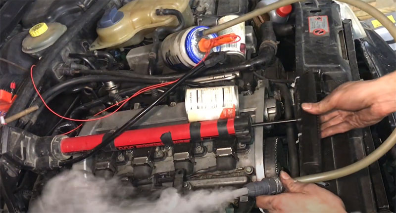
B. Smoke Test:
If available, a smoke machine can fill the intake system with smoke.
Any escaping smoke will pinpoint leak locations instantly.
3.2.5 Check for Internal Intake Issues
Some issues may not be external leaks, but internal problems, such as:
Leaking intercooler (especially if full of oil)
Loose intake manifold bolts or gaskets
Cracked plastic intake runners or turbo piping
Leaking or stuck open EGR valve (on some Audi diesel engines)
If these parts are compromised, the pressure may drop before reaching the cylinders — leading to inaccurate boost readings and P0236.
3.2.6 Fix Detected Leaks or Replace Faulty Components
Tighten clamps and fittings to spec
Replace cracked hoses or broken connectors
Clean or replace the intercooler if it’s oil-saturated or damaged
Use high-temp silicone couplers and proper torque settings
After all repairs, clear the fault codes, and then perform a test drive under boost conditions (e.g., hard acceleration in 3rd gear) to verify that P0236 doesn’t return.
If you’ve ruled out sensor problems and boost leaks, the next critical step in diagnosing DTC P0236 is to inspect the turbocharger’s wastegate system and the boost control solenoid. These components directly regulate how much pressure the turbocharger generates. If they malfunction, the MAP sensor may detect abnormal boost levels—leading to a boost correlation fault.
Let’s break it down thoroughly:
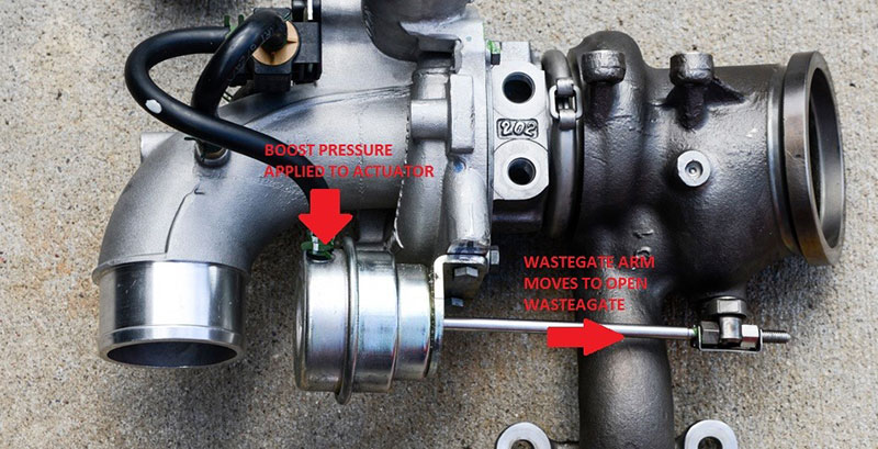
3.3.1. Understanding How the Wastegate System Works
The wastegate is a valve that controls the flow of exhaust gases to the turbocharger’s turbine:
Closed Wastegate = More exhaust to the turbine = More boost
Open Wastegate = Less exhaust to the turbine = Less boost
The wastegate is controlled either:
Mechanically via a pressure-actuated actuator, or
Electronically via a boost pressure control solenoid (N75 valve) and vacuum actuator.
3.3.2. How to Inspect the Wastegate and Boost Control System
A. Check Wastegate Actuator (Mechanical or Vacuum-Operated)
1. Locate the actuator — usually mounted near the turbo.
2. Inspect the wastegate actuator arm:
Ensure it’s not loose, disconnected, or seized.
It should move smoothly by hand (engine off). Use a mirror or flashlight if visibility is limited.
3. Check for corrosion or bent linkages that could prevent movement.
4. Use a vacuum pump or hand-held pressure tester to:
Apply pressure/vacuum to the actuator
Watch for actuator rod movement (typically 5–10 mm)
No movement? The diaphragm might be torn or the actuator is stuck.
💡 Tip: A stuck-closed wastegate = overboost. A stuck-open wastegate = underboost. Both can trigger P0236.
B. Inspect the Boost Control Solenoid (N75 Valve – Common on VAG engines)
Locate the N75 valve (usually mounted on the firewall or near the turbo).
Visually inspect:
Vacuum hoses connected to the valve for cracks, disconnections, or oil contamination.
The electrical connector — make sure it’s clean and snug.
Test electrical resistance of the N75 solenoid with a multimeter:
Typical resistance: 25–35 ohms (varies by model — check spec)
With a scan tool or VCDS:
Run output tests to command the N75 and listen for audible clicks
Monitor duty cycle of the valve under boost conditions
🧪 Optional Functional Test:
Apply 12V to the solenoid briefly while watching airflow through the vacuum lines to verify switching.
C. Check for Vacuum Supply Issues (if wastegate is vacuum-operated)
Inspect the vacuum reservoir and check valves
Ensure there are no leaks in the vacuum lines feeding the actuator
Test for steady vacuum using a handheld vacuum pump — many faults here are caused by poor vacuum rather than a bad actuator
D. Check Turbocharger Vane or Actuator (on Variable Geometry Turbos – VGT)
Some modern Audi diesel engines use VGT (Variable Geometry Turbochargers):
These use electronic actuators or vacuum pods to move vanes that control boost
Scan for actuator faults or use basic settings in VCDS to command the vane sweep test
Common failures:
Jammed vanes due to carbon buildup
Failed position sensors
Faulty electronic actuator motors
3.3.3. After Inspection: What to Do Next
If the actuator is seized or unresponsive ➜ Replace it
If vacuum lines are leaking ➜ Replace hoses or fix connections
If N75 valve is stuck or shorted ➜ Replace the valve
If the wastegate linkage is loose ➜ Tighten or replace the arm
If using VGT and the sweep test fails ➜ Clean or replace turbo/actuator
Clear the fault codes and perform a boost test under load (3rd or 4th gear acceleration). If the wastegate and boost control system are functioning properly, the turbo should produce boost that matches ECU expectations—resolving P0236.
When diagnosing DTC P0236 on an Audi, a frequently overlooked issue lies within the electrical circuit—specifically, the wiring harness and ECU signal path between the Boost Pressure Sensor (MAP Sensor) and the Engine Control Unit (ECU). Faulty wiring or poor connectivity can lead to inaccurate sensor readings, intermittent voltage spikes, or even total signal loss, all of which can trigger the P0236 fault code.
Tools You’ll Need:
Digital multimeter (with voltage and continuity testing)
Back-probing pins
Electrical contact cleaner
Wiring diagram for your Audi model (consult service manual or factory data)
3.4.1. Visual Inspection of Wiring Harness
Begin by locating the MAP sensor wiring harness—usually a 3- or 4-pin connector situated near the intake manifold or throttle body.
Trace the wiring back from the sensor toward the ECU.
Look for obvious signs of damage:
Chafing or rubbing against engine parts
Burnt or melted insulation
Corrosion at connectors or terminals
Signs of rodent damage or splicing
➡ Fix:
If you find damaged wiring or loose pins, repair the affected section with heat-shrink butt connectors or solder and seal with heat-shrink tubing. Always ensure the wire gauge and shielding remain intact.
3.4.2. Pin-by-Pin Continuity Check
Disconnect the MAP sensor and ECU connectors.
Refer to the wiring diagram to identify the signal wire, 5V reference, and ground.
Use your multimeter in continuity mode to check:
Sensor signal wire → ECU input pin
5V reference → ECU 5V output pin
Ground → ECU ground pin
➡ Fix:
If continuity is lost or resistance is above spec (>1 ohm), locate and repair the break, corrosion, or short circuit.
3.4.3. Voltage Testing Under Load
With the sensor reconnected and the ignition ON (engine off), back-probe the connector:
5V reference line should read ~5.0V
Ground line should read close to 0V
Signal wire should vary depending on sensor input (usually 1.5V–4.5V)
Start the engine and observe if the signal voltage changes with engine RPM or throttle input. If the signal is flat or erratic, suspect wiring issues or ECU failure.
➡ Fix:
Clean the connector contacts using electrical contact cleaner, and tighten or re-pin the terminals if needed.
3.4.4. Check for Short-to-Ground or Short-to-Voltage
Use the multimeter to test if any of the sensor wires are:
Shorted to ground
Shorted to power
Shorted to each other (internal harness damage)
➡ Fix:
If a short is found, isolate and repair the damaged section, and re-test after repair.
3.4.5. Test the ECU Pin Integrity
If all wiring checks out but DTC P0236 persists, the ECU input pin (where the sensor signal enters the ECU) might be:
Internally damaged
Corroded
Failing intermittently due to heat or vibration
You can verify this by temporarily replacing the ECU with a known good unit (if available), or using an oscilloscope to examine signal waveform stability.
➡ Fix:
If confirmed, an ECU repair or replacement may be necessary. Reflash or recode as required based on your Audi model.
✅ Pro Tip: After completing all wiring and ECU-related repairs, clear all DTCs and perform a test drive under boost conditions. Use live data monitoring to ensure the MAP sensor is reading pressure values correctly and no abnormal spikes occur.
After completing all necessary inspections and repairs, it’s time to validate your work and confirm that the issue has been fully resolved.
1. Clear All Stored DTCs
Using your diagnostic scan tool, clear all Diagnostic Trouble Codes (DTCs) from the system. This step ensures that you’re starting fresh and that any reappearance of DTC P0236 will indicate a current and active issue, not a historical fault.
⚠️ Important: Do not clear the codes before completing repairs. Doing so may erase valuable freeze frame data and could cause the ECU to suppress the code temporarily, leading to false confidence.
2. Perform a Test Drive Under Load
Next, take the vehicle on a controlled test drive, ideally under varying throttle conditions and engine loads — especially wide-open throttle (WOT) scenarios where the turbocharger is most active.
During this drive:
Observe real-time boost readings using live data from the scan tool.
Ensure that requested boost and actual boost are closely aligned without significant deviation.
Pay attention to any drivability symptoms such as sluggish acceleration, overboost/underboost behavior, or check engine light reactivation.
3. Rescan the Vehicle
After the test drive, return to the diagnostic tool and perform a full system rescan.
If no DTCs reappear, and the vehicle performs normally under load, this confirms the fault has been successfully resolved.
If P0236 returns, even intermittently, re-evaluate the boost control circuit, MAP sensor integrity, and wiring — particularly under heat or vibration, which may cause intermittent faults.
For added confidence, it’s a good idea to record and save post-repair live data logs. This not only documents your successful repair but can also be used for customer communication or future reference.
At AutoExplain, we specialize in remote ECU coding, diagnostics, and technical support for modern vehicles like Audi, Mercedes, BMW, and more. Whether you’re stuck on a fault code like P0236, need help with boost sensor calibration, or want to learn how to use professional tools like ODIS or DTS Monaco, our experts are ready to guide you.
👉 Get instant access to technical guides, repair documentation, and expert help — starting at just $50/year.
👉 Or book a 1-on-1 remote session with a specialist for in-depth support on coding, flashing, or advanced diagnostics.
=> Discover AutoExplain’ service here
DTC P0236 on Audi vehicles — indicating a Turbocharger Boost Sensor A Circuit Range/Performance issue — may seem intimidating at first, but with a clear, step-by-step diagnostic approach, it becomes entirely manageable. Whether the root cause lies in a faulty MAP sensor, a hidden boost leak, a failing wastegate actuator, or even damaged wiring, this fault can be accurately diagnosed and permanently resolved using the right tools, procedures, and technical insight.
By carefully inspecting each component of the boost control system, comparing actual vs. requested boost, and verifying your repairs through a proper test drive and rescan, you can restore your Audi’s full performance, fuel efficiency, and reliability.
Don’t let P0236 slow you down — diagnose it like a pro, and fix it with confidence.